
- Renewable Generation
- Waste-to-Energy
- Circular Economy
- Turnkey EPC
Waste-to- Energy
Mass-Burn | RDF | Landfill Gas | Sludge Digestion | Flue-Gas Cleaning | Ash
Power from what a city throws away.
Waste-to-energy recovers electricity and heat from municipal, industrial and sewage wastes that cannot be recycled, cutting the volume sent to landfill by about 90 %. BARREL supports cities and industries from waste characterisation and concession structuring through design, approvals, equipment, construction and grid connection to long-term operation under strict emission control.
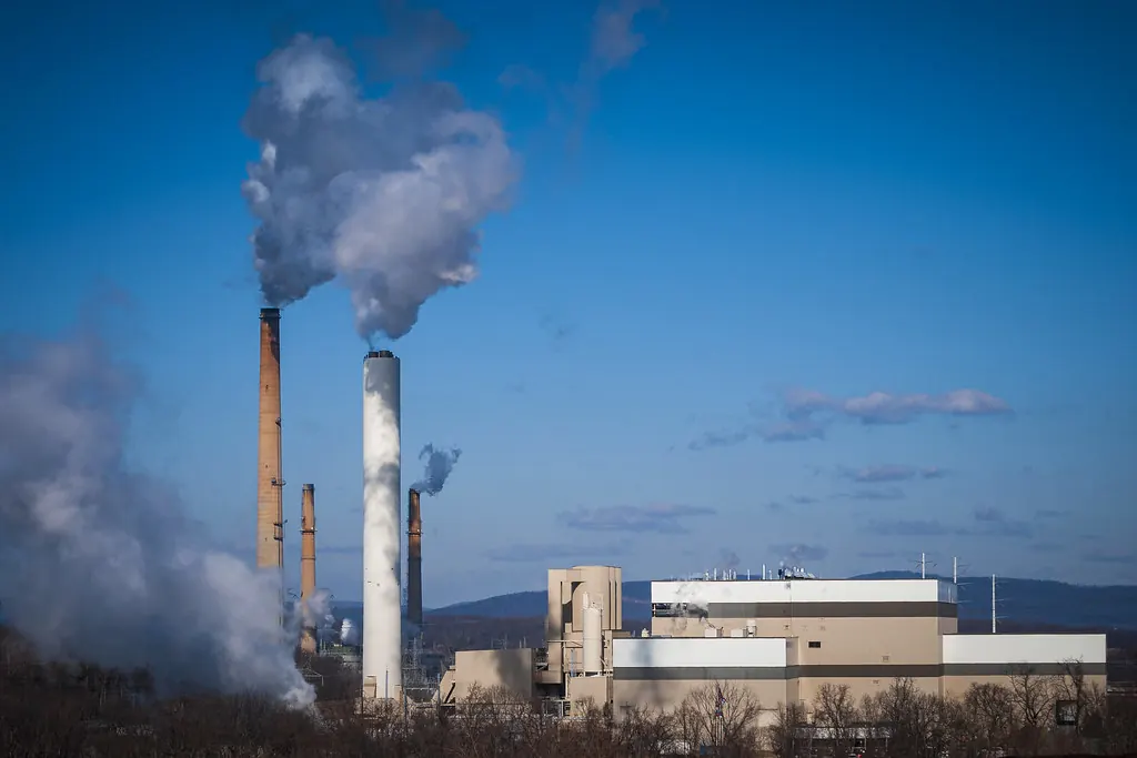
WWaste
Assured quantity and quality of feed
CCombustion
Controlled burning and energy recovery
EEmissions
Flue-gas cleaning to strict limits
- Typical MSW plant
- 300–3,000 TPD
- Mixed MSW LHV (indicative)
- 5–9 MJ/kg
- Net electrical efficiency
- 18–27 %
- Volume reduction
- ~90 %
- Concession life
- 25+ yrs
Section 01
Waste-to-Energy — Overview
Waste-to-energy (WtE) covers the processes that recover usable energy from waste: thermal treatment of solid waste in a boiler, biological digestion of wet organic waste into biogas, and capture of the methane that landfills release.
In the waste hierarchy WtE sits below reduction, reuse and recycling and above landfill. It works best for the residual, non-recyclable fraction after segregation, where it destroys pathogens, recovers energy and leaves a small, inert ash.
1.1Main routes
| Route | Feed | Product | Maturity |
|---|---|---|---|
| Mass-burn grate incineration | Mixed residual MSW | Steam → power and heat | Proven at large scale worldwide |
| RDF combustion / co-processing | Processed high-calorific fraction | Power, or fuel for cement kilns | Proven; quality of RDF is decisive |
| Biomethanation (anaerobic digestion) | Wet organic and food waste | Biogas, compressed biogas, digestate | Proven; needs clean segregated feed |
| Sewage sludge digestion | Primary and secondary sludge | Biogas for CHP at the treatment plant | Proven, widely used |
| Landfill gas recovery | Existing landfills and dumpsites | Gas engines or flaring | Proven; output declines over time |
| Pyrolysis / gasification | Sorted waste, plastics, RDF | Syngas, oil, char | Less proven at scale for mixed MSW |
1.2Why waste-to-energy
01
Less landfill
Reduces waste volume by about 90 % and mass by 70–80 %, saving scarce land near cities.
02
Firm power
Runs round the clock at 80–90 % availability, independent of sun and wind.
03
Lower methane
Avoids the methane that buried organic waste releases, a strong greenhouse gas.
04
Public health
Destroys pathogens and ends open dumping and dumpsite fires.
05
Heat and steam
Can supply process steam or district heating as well as electricity.
06
Material recovery
Metals are recovered from ash; treated bottom ash can be used in road works where rules allow.
Section 02
How a Mass-Burn Plant Works
In a mass-burn plant, waste is tipped into a bunker, mixed by crane and fed onto a moving grate. It dries, ignites and burns out as it travels down the grate, and the hot gases pass through a boiler that raises steam for a turbine.
Combustion is held above 850 °C for at least two seconds after the last air injection, which is the main defence against dioxins and the basis of international emission rules.
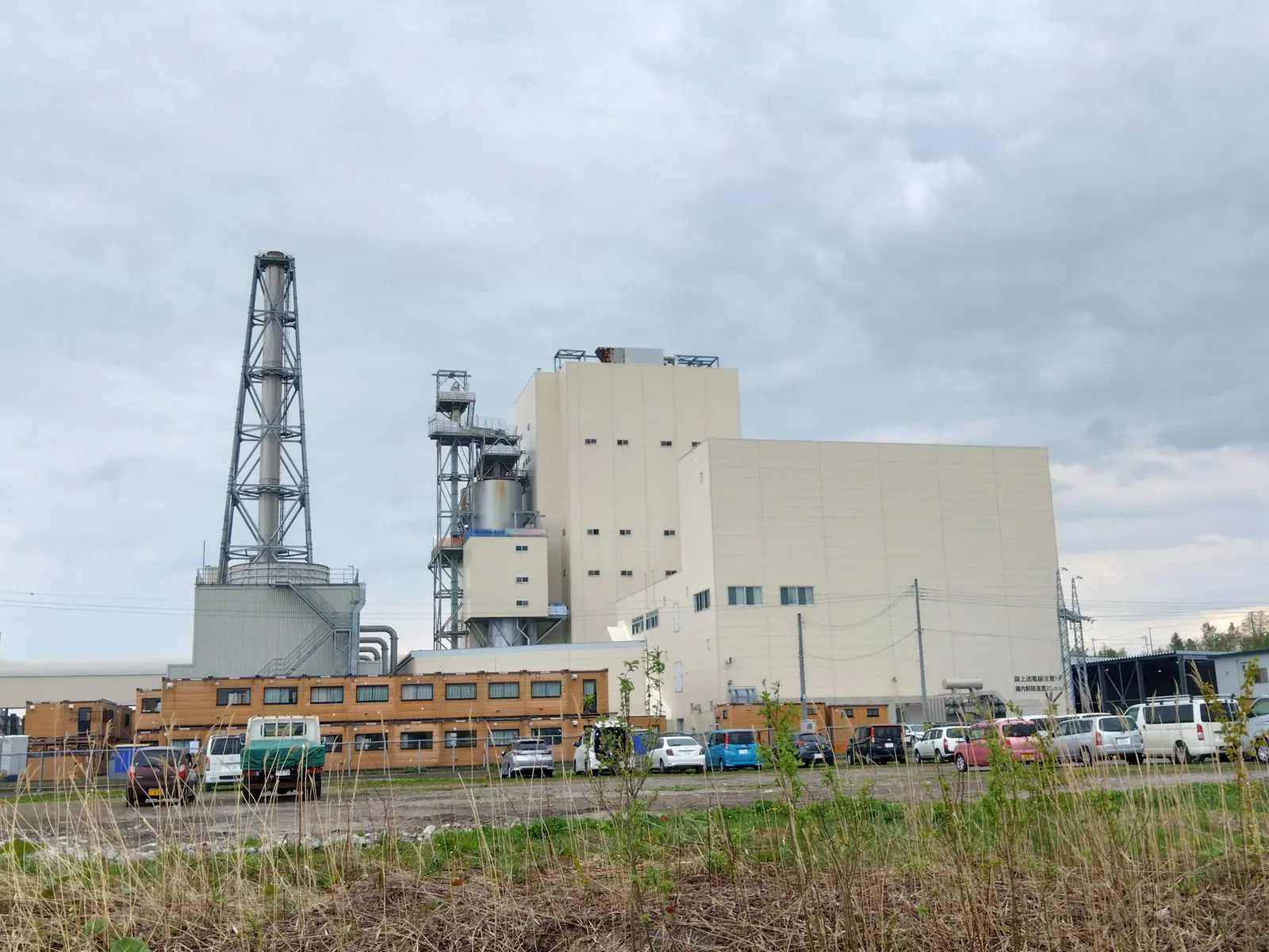
2.1Path of the waste and the gas
- Weighbridge
- Tipping hall
- Bunker
- Crane & hopper
- Grate furnace
- Boiler
- Flue-gas cleaning
- Stack
2.2Combustion and energy recovery
Furnace and grate
5- Reciprocating, roller or travelling grate
- Primary air under the grate, secondary air above
- 850 °C for 2 seconds residence time
- Auxiliary burners for start-up and low calorific value
- Bottom ash discharged to a wet or dry extractor
Boiler and turbine
5- Water-wall furnace and radiant passes
- Superheaters protected against chloride corrosion
- Steam typically 40–45 bar, 400 °C (higher with special alloys)
- Condensing or extraction steam turbine
- Air-cooled or water-cooled condenser
Section 03
Waste Streams and Technology Choices
The waste decides the technology. Dry, mixed residual waste suits combustion; wet organic waste suits digestion; old landfills offer gas; and some industrial wastes need dedicated incinerators.
01
Mass-burnMunicipal solid waste
Residual MSW burned as received on a grate, with minimal pre-treatment; the most proven route for large cities.
02
RDFRefuse-derived fuel
Waste shredded, screened and dried to remove inerts and organics; the light, combustible fraction is burned in a dedicated boiler or co-processed in cement kilns.
03
CaptiveIndustrial waste
Non-hazardous process residues, packaging and rejects burned for steam; hazardous wastes go to licensed incinerators under separate rules.
04
LFGLandfill gas
Wells and pipes collect gas of roughly 45–60 % methane from closed or active landfills to run gas engines or a flare.
05
DigestionSewage sludge
Anaerobic digesters at treatment plants turn sludge into biogas for combined heat and power, and the digested sludge is dewatered.
06
Biogas / CBGFood and wet waste
Segregated organic waste digested to biogas, upgraded to compressed biogas or burned in engines; the digestate becomes compost.
Pyrolysis and gasification
Pyrolysis, gasification and plasma processes are often promoted for mixed municipal waste. Several large projects abroad have failed or been abandoned because of variable feed, tar and reliability problems. They can suit well-sorted streams such as plastics or uniform RDF, but for mixed MSW they should be treated as less proven at scale and checked against reference plants with years of operating data.
Section 04
Waste Characterisation, Calorific Value and Plant Sizing
A WtE plant is only as good as the waste it receives. Quantity, composition, moisture and calorific value must be measured over all seasons before the plant is sized.
3.1Power from a waste combustion plant
Net electrical output
P (MW) = W × LHV × η / 3.6
Example (indicative): 1,000 TPD ≈ 41.7 t/h at 8 MJ/kg and η = 0.22 → about 20 MW
W × LHV gives the heat input in GJ per hour; dividing by 3.6 converts it to MW. Mixed Indian MSW often has a lower calorific value, especially in the monsoon, so many plants pre-process waste or use the RDF route.
| Symbol | Meaning |
|---|---|
| W | Waste fed to the furnace, tonnes per hour |
| LHV | Lower heating value of the waste as fired, MJ/kg (= GJ/t) |
| η | Net electrical efficiency, about 0.18–0.27 |
| 3.6 | GJ per MWh, converts GJ/h to MW |
3.2Studies before design
Waste survey
6- Daily arrivals at weighbridges over at least a year
- Seasonal composition by hand sorting
- Moisture, ash and volatile content
- Calorific value by bomb calorimeter
- Chlorine, sulphur and heavy-metal content
- Growth forecast and segregation targets
Site and logistics
6- Distance from collection areas and transfer stations
- Truck routes, queuing and odour control
- Buffer zone from housing
- Water source and cooling option
- Grid or steam customer nearby
- Ash disposal or reuse outlet
Indian municipal waste often has high moisture and inert content. A design range of calorific values, not a single number, should define the furnace firing diagram.
Section 05
Flue-Gas Cleaning, Emission Norms and Ash Handling
Flue-gas cleaning is the most important and often the most costly part of a WtE plant. Modern systems remove dust, acid gases, nitrogen oxides, heavy metals and dioxins in several stages, with continuous emission monitoring at the stack.
Ash leaves the plant in two streams: bottom ash from the grate and fly ash plus cleaning residues from the gas path. Each needs its own handling route.
4.1Typical cleaning train
- SNCR (urea / ammonia)
- Spray dryer or dry lime
- Activated carbon injection
- Bag filter
- Wet scrubber (optional)
- SCR (optional)
- CEMS
- Stack
4.2Key emission parameters (indicative)
Limits differ by country and change over time; the plant must meet the norms in its consent and the latest notifications of the pollution control authorities.
| Pollutant | Control method | Typical limit order |
|---|---|---|
| Particulate matter | Bag filter | 10–50 mg/Nm³ |
| HCl, SO₂, HF | Lime or sodium bicarbonate, scrubber | HCl 10–50, SO₂ 50–200 mg/Nm³ |
| NOx | Combustion control, SNCR or SCR | 200–400 mg/Nm³ |
| Mercury and heavy metals | Activated carbon, bag filter | Hg about 0.05 mg/Nm³ |
| Dioxins and furans | 850 °C / 2 s, quench, carbon, bag filter | 0.1 ng TEQ/Nm³ |
| CO and total organic carbon | Good combustion control | CO 50–100, TOC 10–20 mg/Nm³ |
4.3Ash and residues
Bottom ash (about 20–25 % of input)
4- Quenched and discharged from the grate
- Ferrous and non-ferrous metals recovered
- Weathered and tested for leaching
- Reused as aggregate where rules allow, otherwise landfilled
Fly ash and APC residue (about 2–5 %)
4- Contains salts, heavy metals and dioxins
- Treated as hazardous in most jurisdictions
- Stabilised with cement or chemicals
- Sent to a secured hazardous-waste landfill
Section 06
Plant Systems and Equipment
A WtE plant combines a waste-handling facility, a thermal power station and a chemical gas-cleaning plant on one site.
| System | Main equipment | Design points |
|---|---|---|
| Reception | Weighbridges, tipping hall, bunker | 5–7 days of storage, negative pressure against odour |
| Feeding | Grab cranes, hoppers, rams | Mixing to even out calorific value, fire detection |
| Pre-processing (RDF) | Shredders, trommels, magnets, air classifiers, dryers | Removal of inerts and wet organics |
| Furnace and boiler | Grate, refractory, water walls, superheaters | Corrosion and fouling protection, cleaning systems |
| Power island | Steam turbine, generator, condenser | Matching to steam conditions and part-load operation |
| Gas cleaning | Reactors, silos, bag filter, ID fan, stack | Redundancy, CEMS, reagent logistics |
| Ash and water | Ash extractors, conveyors, leachate treatment | Zero liquid discharge where required |
5.1Biogas and landfill gas package
- Digesters with mixing and heating
- Gas holders and safety flares
- Gas cleaning (H₂S, moisture, siloxanes)
- Gas engines or micro-turbines
- Upgrading to compressed biogas
- Landfill wells, header pipes and blowers
Section 07
Grid Connection, Steam Supply and Auxiliary Load
WtE plants are usually near cities and connect at 11, 33, 66 or 132 kV. Their own consumption is high, so the export figure, not the gross rating, matters in every contract.
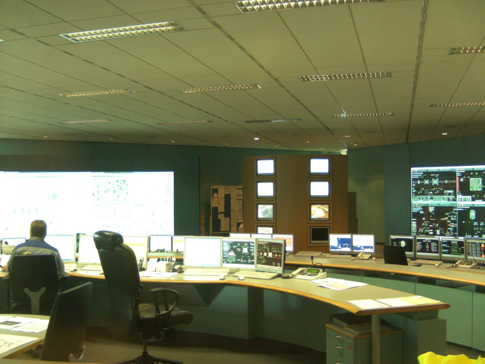
- Auxiliary consumption often 15–25 % of gross output
- Connectivity and evacuation study with the utility
- Metering, telemetry and scheduling with the load despatch centre
- Black-start and island operation for plant safety
- Steam export to nearby industry where demand exists
- District heating or cooling in suitable climates
Combined heat and power raises total efficiency well above that of power-only plants, but needs a reliable steam or heat customer close to the site.
Section 08
Municipal Concessions, Rules and Approvals
In India most WtE plants are public-private partnerships: the urban local body provides land and guarantees waste, and the developer designs, builds, finances and operates the plant for a fixed period.
The Solid Waste Management Rules, 2016 broadly require segregation at source and say that non-recyclable waste of sufficient calorific value should go to energy recovery or RDF rather than landfill, with RDF offered to nearby cement and power plants. Emission standards for WtE plants are set under these rules and by the pollution control boards.
- 1Waste survey and feasibility study with the city
- 2Concession structuring: waste quantity, quality and tipping fee
- 3Bid documents, tender and concession agreement
- 4Land lease and site handover
- 5Environmental impact assessment and public hearing as applicable
- 6Consent to establish from the state pollution control board
- 7Grid connectivity and power purchase agreement
- 8Financial close and EPC award
- 9Consent to operate before commissioning
7.1Concession risks to settle up front
Waste supply
4- Minimum guaranteed tonnage per day
- Calorific value band and penalties
- Segregation commitments of the city
- Who bears the cost of rejects
Payments
4- Tipping fee per tonne and its escalation
- Power tariff and payment security
- Termination and compensation terms
- Change-in-law protection for new emission norms
Section 09
Turnkey EPC Delivery
BARREL coordinates the whole plant under one contract or manages separate packages for waste handling, the boiler island, the power island and gas cleaning.
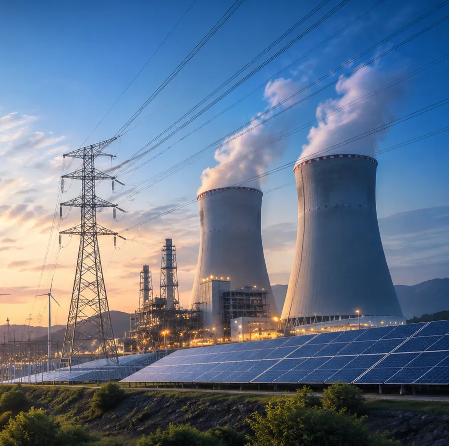
Civil and buildings
4- Tipping hall and bunker
- Boiler and turbine buildings
- Stack and ash yards
- Roads, weighbridges, drainage
Thermal island
4- Grate and boiler
- Flue-gas cleaning
- Steam turbine-generator
- Condenser and cooling
Electrical and controls
4- Transformers and switchyard
- DCS and CEMS
- Fire protection
- Transmission line and bay
8.1Typical schedule (500–2,000 TPD)
- Waste survey 6–12 mo
- Concession & approvals 12–18 mo
- Construction 24–36 mo
- Commissioning 4–6 mo
Section 10
Operation and Maintenance
WtE operation is demanding: the fuel changes truck by truck, chlorides attack the boiler and every hour of emissions is on record. Skilled operators and planned outages keep availability above 85 %.
- Crane operators mixing the bunker for steady calorific value
- Combustion control on temperature, oxygen and steam flow
- Continuous emission monitoring and reporting
- Periodic dioxin and heavy-metal stack testing
- Boiler cleaning and superheater inspections
- Refractory and grate bar replacement in planned outages
- Reagent, ash and leachate logistics
- Odour, fly and vermin control at the bunker
- Public reporting and community engagement
Section 11
Finance and Commercial Models
A WtE plant earns from two sides: a gate or tipping fee for treating waste and the sale of power, steam or fuel. Recovered metals and carbon credits can add smaller revenues.
| Item | Typical range (India, indicative) |
|---|---|
| Capital cost (MSW combustion) | ₹15–25 crore per MW of gross capacity |
| Power tariff | Regulator-determined, often ₹7–8 per kWh |
| Tipping fee | Low or nil in many Indian cities; high in Europe and East Asia |
| Plant availability | 80–90 % for well-run plants |
| Concession period | 20–30 years |
| Other revenues | Steam sales, metals from ash, carbon credits, compost from digestate |
Figures are indicative for early screening only; waste quality and the payment terms of the city decide whether a project is bankable.
Section 12
BARREL Services for Waste-to-Energy
One partner for cities and industries from the first waste survey to decades of compliant operation, backed by BARREL's network of consultants, equipment makers and contractors.
- Waste surveys and characterisation
- Technology selection and feasibility
- Concession and tender support for cities
- DPR, EIA and consent support
- Owner's engineer and lender's engineer
- Boiler, gas-cleaning and turbine sourcing
- Turnkey EPC / EPCM
- Biogas and landfill gas projects
- Grid connectivity and PPA support
- Project finance facilitation
- O&M and emission compliance
- Renovation of existing plants
Project desk
Build your waste-to-energy project with BARREL
From the first waste survey to clean, firm power.
Planning a city WtE plant, an RDF facility, a biogas or landfill gas project, or upgrading an existing plant — tell us about the waste and the site and we will respond with the next steps.
Project categories
- MSW mass-burn
- RDF plant
- Industrial waste
- Landfill gas
- Sewage sludge digestion
- Biogas / CBG