
- Renewable Generation
- Offshore Wind
- Floating Wind
- Marine Infrastructure
Offshore & Floating Wind
Monopile | Jacket | Tripod | Spar | Semi-Sub | TLP | Export Cables | Substations
Stronger, steadier winds out at sea.
Offshore wind places large turbines at sea, where winds are stronger and steadier than on land and there is room for very large rotors. Fixed-bottom foundations serve shallower waters; floating platforms open up deep water. BARREL provides and coordinates offshore wind work from metocean and seabed studies and concept design through approvals, marine logistics, grid connection and long-term operation.
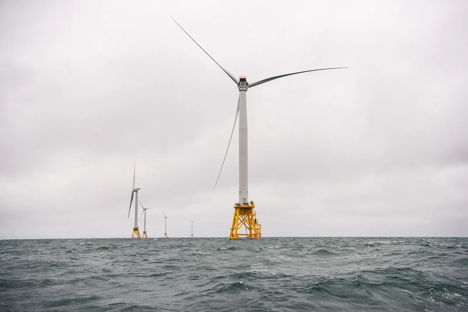
WWind
Higher, steadier wind speeds at sea
SSeabed
Water depth and soil decide the foundation
CCable
Export cables and substations bring power ashore
- Turbine size today
- 8–15+ MW
- Fixed / floating depth
- 0–60 m / 60 m+
- Capacity factor, good sites
- 35–50 %
- Array & export AC
- 66–220 kV
- Design life
- 25–30 yrs
Section 01
Offshore Wind — Overview
An offshore wind farm is a group of turbines on foundations in the sea, linked by inter-array cables to an offshore substation, which sends power ashore through export cables to an onshore substation and the grid.
Winds at sea are less disturbed by terrain, so they are stronger and more constant. That gives more energy per turbine, but every task, from survey to repair, is done in a marine environment, which shapes cost, schedule and risk.
1.1Why offshore wind
01
Stronger winds
Higher average wind speeds and lower turbulence give higher capacity factors than most land sites.
02
Very large turbines
No road transport limits: rotors over 200 m in diameter can be shipped and installed at sea.
03
Near coastal demand
Coastal cities and industries can be supplied without long land transmission lines.
04
Complements solar
Monsoon and evening winds often peak when solar output is low.
05
Space
Large sites without land acquisition, sited away from shipping lanes and sensitive habitats.
06
Port and industry growth
Fabrication yards, ports and vessels create a new marine industrial base.
1.2Power path of an offshore wind farm
- Turbine
- Inter-array cable
- Offshore substation
- Export cable
- Landfall
- Onshore substation
- Grid
Section 02
Fixed-Bottom Foundations and Floating Platforms
The foundation is chosen from water depth, seabed soil, turbine size and the vessels available. Fixed-bottom foundations dominate today up to about 50–60 m depth; floating platforms take over in deeper water.
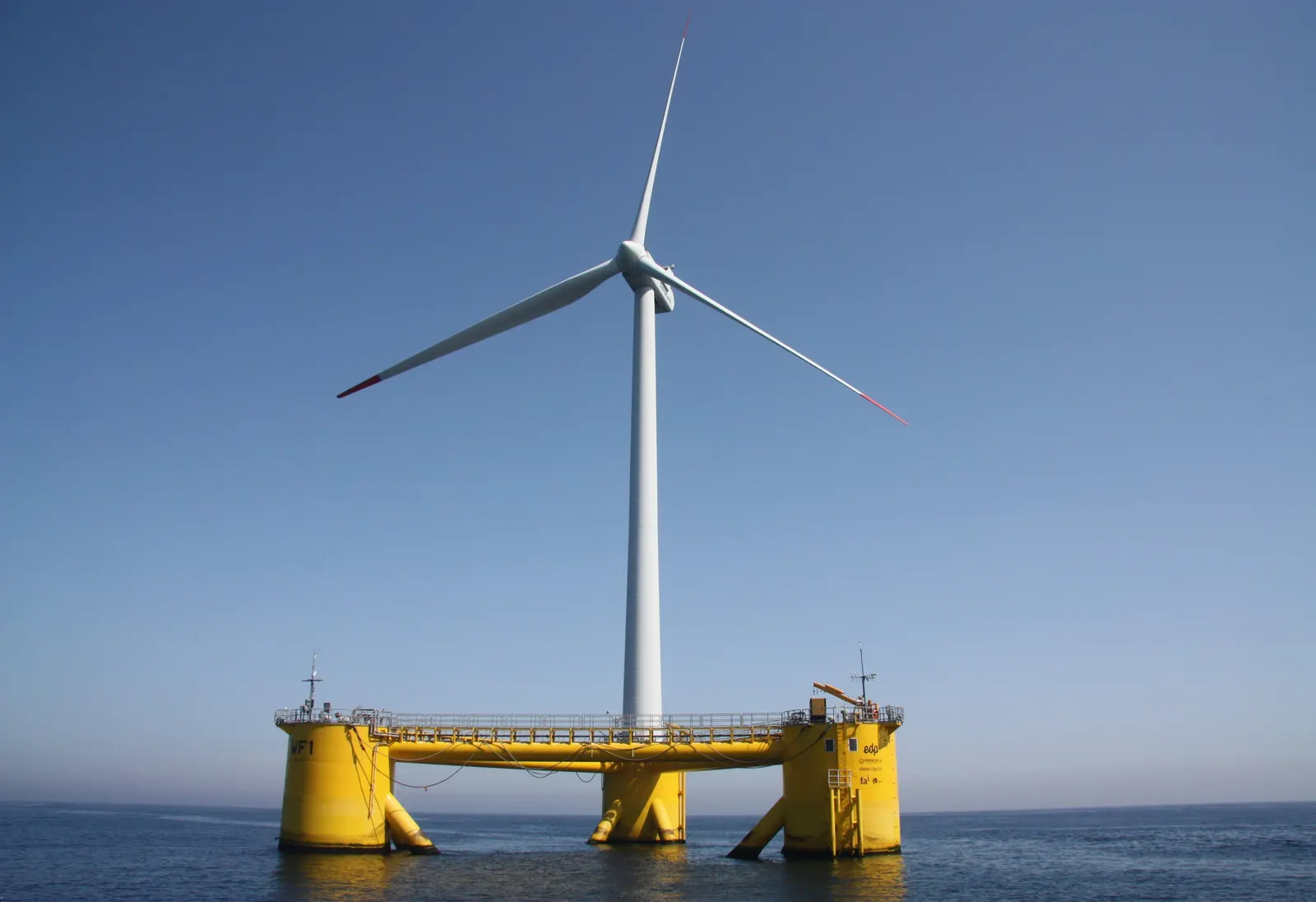
2.1Fixed-bottom
01
0–40 m+Monopile
A single large steel tube, now often 8–11 m in diameter, driven or drilled into the seabed; simple and most widely used.
02
30–60 mJacket
A steel lattice with three or four legs pinned to the seabed by piles; stiff and light for deeper water or hard soils.
03
25–50 mTripod / tripile
A central column on three legs or three piles; spreads load where a single monopile would be too large.
04
Shallow, hard seabedGravity base
A heavy concrete base held by its own weight; avoids piling noise but needs seabed preparation.
2.2Floating
01
Deep waterSpar buoy
A tall, ballasted cylinder with a deep draft for stability; needs 100 m+ depth and deep-water assembly.
02
Most commonSemi-submersible
Three or four buoyant columns linked by pontoons; shallow draft allows assembly at the quayside and tow-out.
03
Small footprintTension-leg platform (TLP)
Buoyant hull held down by taut tendons to anchors; very stable but demanding anchors and installation.
04
Shallow draftBarge
A wide floating hull with a damping pool; compact but more motion in rough seas.
Section 03
Wind Resource, Metocean and Seabed Surveys
Energy rises with the cube of wind speed, so small differences in mean wind speed have a large effect on yield. Waves, currents, tides and the seabed decide what can be built and how much it costs.
Survey campaigns typically run for one to two years before the design is fixed.
3.1Power in the wind
Turbine output
P = ½ × ρ × A × v³ × Cp
Example (indicative): ρ = 1.225 kg/m³, rotor 220 m (A ≈ 38,000 m²), v = 9 m/s, Cp = 0.45 → P ≈ 7.6 MW, below rated power
Output rises with the cube of wind speed until the turbine reaches its rated power, after which the blades pitch to hold output constant. The theoretical maximum Cp is about 0.593 (the Betz limit); real rotors reach about 0.45–0.50.
| Symbol | Meaning |
|---|---|
| P | Power extracted, W |
| ρ | Air density, about 1.225 kg/m³ at sea level and 15 °C |
| A | Rotor swept area, π × (D/2)², m² |
| v | Wind speed at hub height, m/s |
| Cp | Power coefficient of the rotor |
3.2Survey campaign
Wind
5- Floating LiDAR buoys
- Fixed met mast or platform LiDAR
- Long-term correlation with reanalysis data
- Wake and layout modelling
- Cyclone and extreme wind study
Metocean
5- Wave height, period and direction
- Currents and tides
- Water level and storm surge
- Sea temperature and marine growth
- Extreme and fatigue load cases
Seabed
5- Bathymetry by multibeam echo sounder
- Geophysical: side-scan sonar, sub-bottom profiler
- Geotechnical: cone penetration tests and boreholes
- Unexploded ordnance and obstruction search
- Benthic habitat and archaeology survey
Section 04
Turbines and Main Components
Offshore turbines are built for salt air, high loads and limited access: corrosion protection, redundancy and remote monitoring matter as much as rated power.
| Component | Function | Offshore design points |
|---|---|---|
| Rotor and blades | Capture wind energy | Blades over 100 m long; leading-edge erosion protection |
| Nacelle and drivetrain | Gearbox or direct-drive generator | Sealed, dehumidified, corrosion-protected; crane for parts |
| Tower | Carries the nacelle at hub height | Coated steel sections; internal platforms and lift |
| Transition piece | Links tower to foundation | Boat landing, access ladder, work platform, J-tubes for cables |
| Foundation or floater | Holds the turbine to the seabed | Fatigue, scour protection, cathodic protection |
| Mooring and anchors (floating) | Keep the floater on station | Chains, synthetic ropes, drag, suction or pile anchors |
| Control and SCADA | Operates and protects the turbine | Remote reset, condition monitoring, cyclone strategy |
Section 05
Marine Installation, Vessels and Ports
Installation is a chain of marine operations planned around weather windows. The availability of suitable vessels and a port with heavy-load quays often sets the schedule.
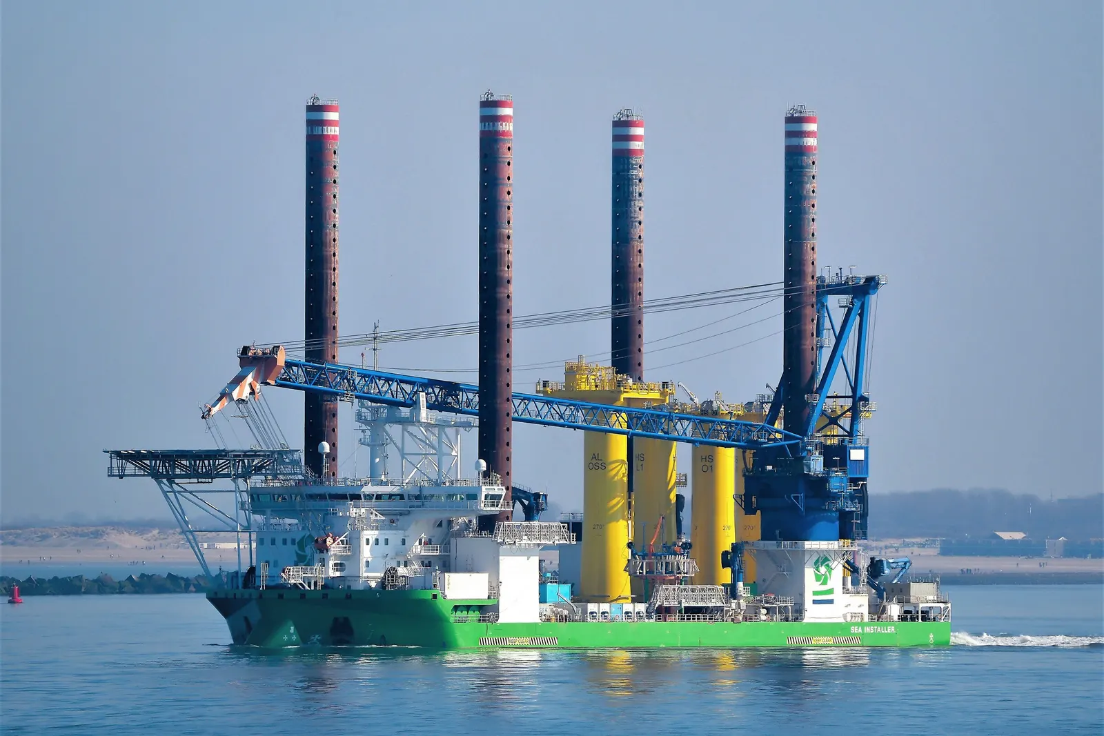
5.1Main vessel types
01
TurbinesJack-up installation vessel
Lowers its legs to the seabed and lifts itself clear of the waves to install towers, nacelles and blades with a large crane.
02
FoundationsHeavy-lift vessel
Floating crane vessel for monopiles, jackets and substation topsides.
03
CablesCable-lay vessel
Carries cable on a turntable and lays array and export cables, with trenching or burial tools.
04
Floating windTugs and anchor handlers
Tow floating units from port and hook up mooring lines.
05
SupportSurvey and support vessels
Seabed checks, UXO clearance, scour protection placement and crew transfer.
5.2Typical installation sequence
- 1Seabed preparation and scour protection where needed
- 2Foundation installation (piling, jacket placement or floater mooring)
- 3Transition piece and offshore substation installation
- 4Inter-array and export cable lay, burial and pull-in
- 5Turbine installation: tower, nacelle, blades
- 6Hook-up, energisation and commissioning
5.3What a wind port needs
- Heavy-load quay and laydown area for foundations and blades
- Water depth and air draft for installation vessels
- Assembly area and quayside cranes for floating units
- Fabrication yards for jackets, piles and transition pieces
- O&M base with crew-transfer berths close to the site
- Road and rail access for components
Section 06
Export Cables, Offshore Substations and Grid
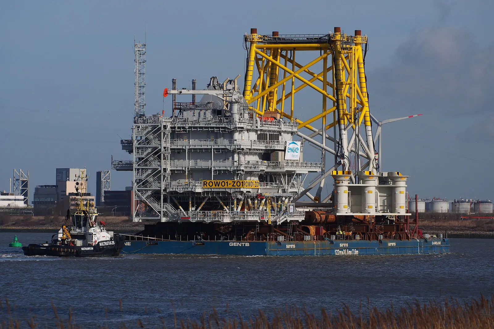
The electrical system collects power from each turbine, steps it up at sea and brings it ashore. Distance from shore decides between high-voltage AC and high-voltage DC export.
| Element | Typical design (indicative) | Notes |
|---|---|---|
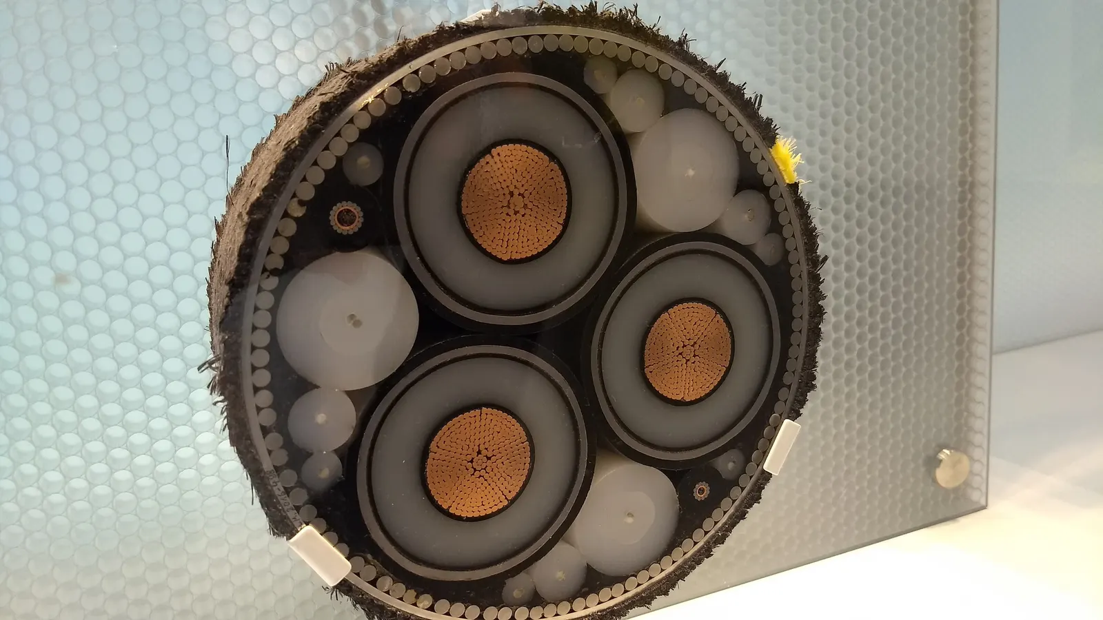
| Inter-array cables | 66 kV AC (132 kV emerging) | Strings of turbines looped to the substation |
| Offshore substation | Transformers, switchgear, reactive compensation | On a jacket or floating hull; some designs omit it near shore |
| HVAC export cable | 132–275 kV three-core | Practical up to roughly 80–100 km before reactive losses grow |
| HVDC export | ±320 kV and above with converter stations | For long distances and very large farms |
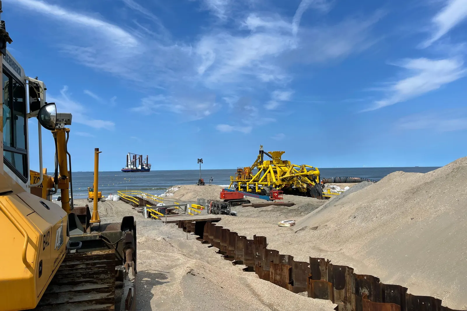
| Landfall | Horizontal directional drilling under the beach | Protects the coast and the cable |
| Onshore substation | Step-up to transmission voltage, compensation, metering | Connection to the state or inter-state grid |
Section 07
India's Offshore Wind Zones and Project Development
India's assessments identify the most promising offshore wind zones off the coast of Gujarat, in the Gulf of Khambhat area, and off Tamil Nadu, around the Gulf of Mannar and the southern tip near Kanyakumari. Tamil Nadu has the stronger winds; Gujarat has shallower water closer to industrial demand.
The national framework assigns zones through central agencies, with seabed leasing, survey data and grid planning coordinated by the government. Tender rules, support schemes and timelines are set and updated by the government and are checked for each opportunity.
- 1Zone identification and preliminary resource data from government agencies
- 2Seabed lease or allocation through the applicable tender or lease process
- 3Metocean, geophysical and geotechnical surveys
- 4Environmental and social impact assessment, including marine life and fisheries
- 5Coastal regulation, maritime, defence and navigation clearances
- 6Grid connectivity and onshore substation planning
- 7Front-end engineering design and foundation concept
- 8Power purchase agreement and financial close
- 9Fabrication, installation and commissioning
Internationally, offshore wind is well established in the North Sea and growing quickly in China, Taiwan, South Korea, Japan and the United States; floating wind is moving from pilot arrays to commercial scale.
Section 08
Operation and Maintenance
O&M is about getting technicians and parts to the turbines safely in a usable weather window. Access strategy, remote monitoring and planned campaigns keep availability high.
8.1Access strategies
01
Near shoreCrew transfer vessel (CTV)
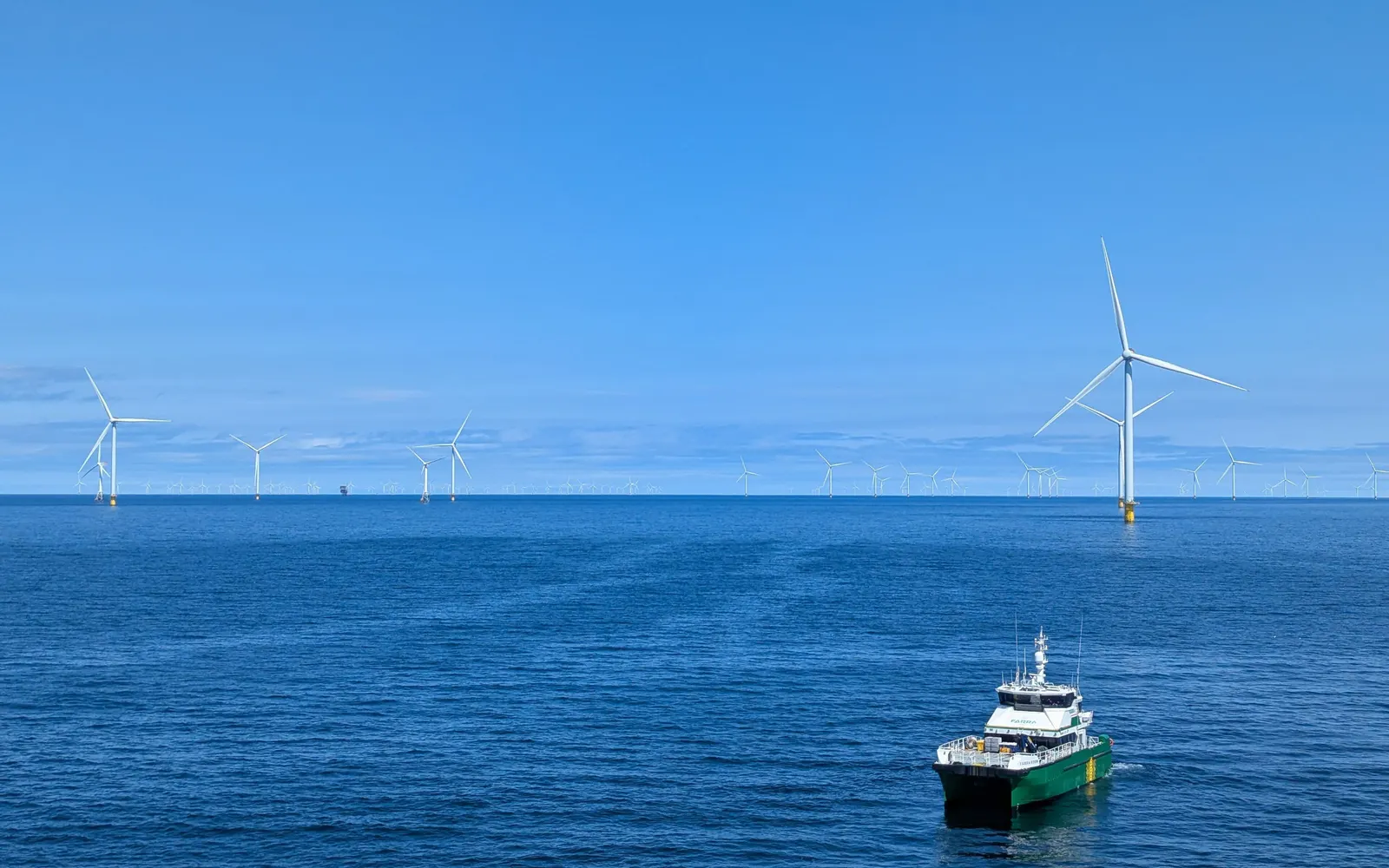
Fast catamarans carrying around a dozen technicians on daily trips from the O&M port; limited by wave height.
02
Far shoreService operation vessel (SOV)
A larger ship staying at the farm for weeks, with a motion-compensated gangway for walk-to-work access.
03
Fast responseHelicopter
Hoists technicians onto nacelles for urgent repairs when sea access is not possible.
04
Major repairsHeavy-lift campaigns
Jack-up vessels for gearbox, generator or blade exchange; floating units may be towed back to port.
8.2Core O&M tasks
- Condition monitoring and remote diagnostics
- Scheduled turbine service visits
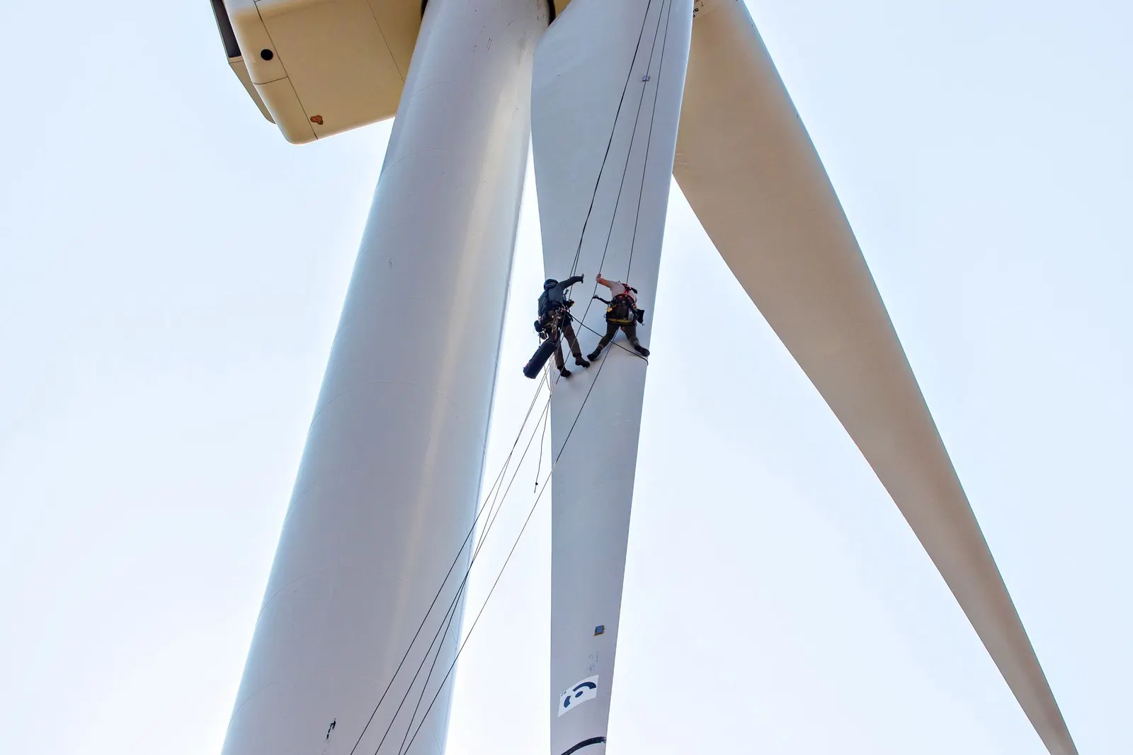
- Blade inspection by drone and leading-edge repair
- Foundation, scour and corrosion surveys
- Cable burial and protection surveys
- Mooring line inspection for floating units
- Offshore substation maintenance
- Weather and sea-state forecasting for access
Section 09
Finance and Commercial Models
Offshore wind is capital-heavy and its first projects in a new market carry higher risk; early projects in many countries have relied on government support, long-term contracts and development finance.
| Item | Typical range (international, indicative) |
|---|---|
| Capital cost | About 2–3 times onshore wind per MW; floating higher today |
| Cost split | Turbines about one third; foundations, cables, installation and grid most of the rest |
| Capacity factor | 35–50 % at good sites |
| Development to operation | Often 6–10 years including surveys and approvals |
| Revenue options | Long-term PPA, contract for difference or viability-gap support, corporate PPAs |
Figures are indicative for early screening only; each project needs its own metocean study, cost estimate and financial model.
Section 10
Standards and the Future of Offshore Wind
Offshore wind design and certification follow international standards; the next steps are larger turbines, floating farms and links to hydrogen and storage.
Key standards
5- IEC 61400-1 wind turbine design requirements
- IEC 61400-3-1 fixed offshore turbines
- IEC TS 61400-3-2 floating offshore turbines
- DNV standards for support structures, floating units, offshore substations and subsea cables
- Type and project certification under the IECRE scheme
What comes next
6- Turbines of 15–20 MW and beyond
- Floating wind arrays at commercial scale
- Offshore HVDC hubs linking several farms
- Green hydrogen from offshore wind
- Hybrid parks with storage and solar
- Cyclone-resilient designs for tropical seas
Section 11
BARREL Services for Offshore Wind
BARREL coordinates survey firms, marine engineers, fabricators, vessel operators, cable suppliers and financiers to support developers, ports and industry entering offshore wind.
- Site screening and pre-feasibility
- Metocean and seabed survey coordination
- Foundation and floating concept studies
- Approvals and stakeholder support
- Owner's engineer and lender's engineer
- Port and supply-chain assessment
- Turbine, foundation and cable sourcing
- Marine logistics and installation planning
- Grid connectivity and PPA support
- Project finance facilitation
- O&M strategy and vessel planning
- Acquisition due diligence
Project desk
Plan your offshore wind project with BARREL
From the first wind buoy to power at the shore.
A developer, port, fabricator or investor looking at offshore or floating wind — tell us about the site, the role you plan to play and your timeline, and we will respond with the next steps.
Project categories
- Fixed-bottom wind farm
- Floating wind
- Offshore substation & cables
- Wind port & logistics
- Supply chain & fabrication
- O&M