
- Thermal Generation
- Cogeneration
- Captive Power
- Turnkey EPC
Cogeneration & Captive Power
CHP | Trigeneration | Waste Heat | Back-Pressure Turbines | DG/GG Sets | Captive
Power and heat from one fuel, at the point of use.
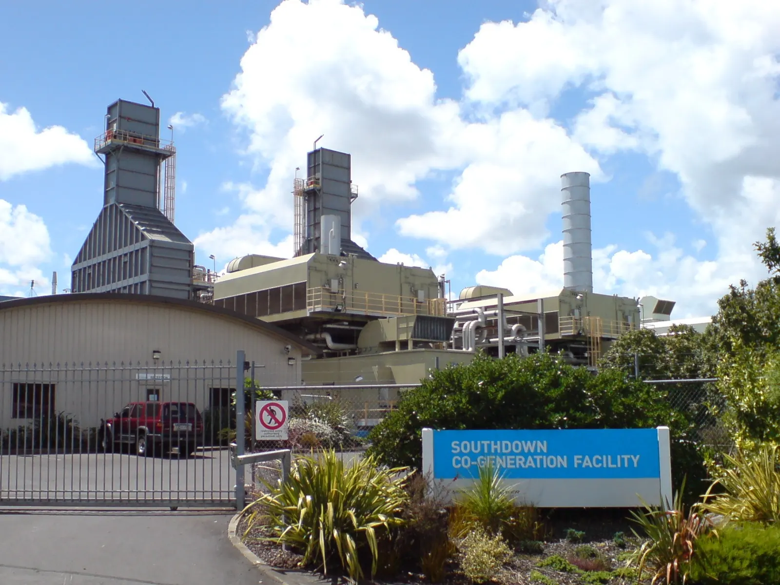
Cogeneration makes electricity and useful heat — steam, hot water or chilled water — from the same fuel, at the factory, hospital or campus that needs both. BARREL plans, builds and operates CHP, waste-heat and captive power plants for industry, from the first steam and power balance to approvals, equipment, construction and long-term operation.
PPower
Electricity for the plant and the grid
HHeat
Steam, hot water or chilled water
BBalance
Matching heat and power demand
- Plant size
- 100 kW–300 MW
- Overall fuel use
- 70–90 %
- Fuel saving vs separate
- 15–40 %
- Asset life
- 20–30 yrs
- Connection
- 0.415–132 kV
Section 01
Cogeneration and Captive Power — Overview
A conventional power station throws away more than half its fuel energy as waste heat. A cogeneration (CHP) plant captures that heat and puts it to work in a process, so the same fuel serves two needs and overall use of fuel energy rises to 70–90 %.
Captive power plants are owned by, or built for, the industries that use their output. They give reliable supply, lower energy cost and control over quality of power, and they are often designed as cogeneration plants.
1.1Who uses cogeneration
| Sector | Heat use | Typical plant |
|---|---|---|
| Sugar and distilleries | Process steam for milling and evaporation | Bagasse-fired boiler with back-pressure or extraction turbine |
| Paper, textiles, chemicals | Medium-pressure process steam | Coal, biomass or gas boiler with steam turbine; gas turbine with HRSG |
| Refineries and fertiliser | High-pressure steam and process heat | Gas turbines with HRSGs, large extraction turbines |
| Cement, steel, glass | Waste heat from kilns and furnaces | Waste-heat recovery boilers and steam or ORC turbines |
| Hospitals, hotels, data centres, campuses | Hot water and cooling | Gas engines with heat recovery and absorption chillers |
1.2Why cogeneration and captive power
01
Lower energy cost
One fuel bill for power and heat; often cheaper than buying grid power and firing a separate boiler.
02
Higher efficiency
70–90 % of fuel energy used, against roughly 35–55 % for power alone.
03
Reliable supply
Islanding from the grid protects continuous processes from outages and voltage dips.
04
Lower emissions
Less fuel burnt for the same output; biomass and waste heat cut fossil CO₂ further.
05
Energy security
Fuel choice and dispatch under the user's control.
06
Use of by-products
Bagasse, rice husk, process off-gases and kiln heat turned into energy.
Section 02
How Cogeneration Works
In a topping cycle, fuel is burnt first to make power and the exhaust or turbine steam then serves the process. In a bottoming cycle, high-temperature process waste heat is recovered first and used to raise steam for power.
The heat-to-power ratio of the site decides the prime mover: steam turbines suit high steam demand, gas turbines and engines suit higher power demand with moderate heat.
2.1Gas engine CHP energy path
- Fuel gas
- Engine
- Generator
- Exhaust boiler
- Jacket water heat
- Absorption chiller
- Process / building
2.2Overall efficiency of a CHP plant
Total CHP efficiency
ηCHP = (E + Q) / F
Heat-to-power ratio = Q / E; fuel saving compared with separate supply = 1 − F / (E / ηe,ref + Q / ηh,ref)
A CHP plant only pays when the recovered heat is really used. The fuel-saving check compares the CHP fuel with the fuel a reference power plant and boiler would burn for the same power and heat.
| Symbol | Meaning |
|---|---|
| E | Net electrical output, kWh |
| Q | Useful heat delivered to the process, kWh (thermal) |
| F | Fuel energy input, kWh |
| ηe,ref | Efficiency of reference power supply, e.g. 0.40–0.50 |
| ηh,ref | Efficiency of reference boiler, e.g. 0.85–0.90 |
Section 03
Cogeneration and Captive Plant Types
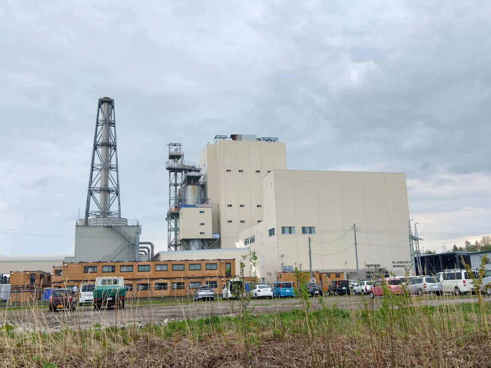
The choice follows the site: the fuel at hand, the pressure and amount of steam needed, and how steady the demand is through the day and year.
01
High steamBack-pressure steam turbine
Boiler steam passes through a turbine and leaves at process pressure; all exhaust steam is used, power follows steam demand.
02
FlexibleExtraction-condensing turbine
Steam is bled at one or more pressures for the process; the rest condenses so power can be made independent of heat demand.
03
Large sitesGas turbine with HRSG
Turbine exhaust raises steam in a heat recovery boiler, with supplementary firing to follow steam demand.
04
Buildings & SMEsGas engine CHP
Engine power plus heat from exhaust, jacket water and lube oil; 0.5–10 MW units, high electrical efficiency.
05
BottomingWaste-heat recovery power
Boilers on kiln, furnace or process exhaust feed a steam turbine or an organic Rankine cycle (ORC) for lower temperatures.
06
CoolingTrigeneration
CHP plus a vapour absorption machine (VAM) turning recovered heat into chilled water for process or air conditioning.
3.1Indicative performance
| Prime mover | Electrical efficiency | Heat-to-power ratio | Heat form |
|---|---|---|---|
| Back-pressure steam turbine | 10–20 % | 4–10 | Process steam |
| Extraction-condensing steam turbine | 15–30 % | 1–8 (adjustable) | Process steam |
| Gas turbine with HRSG | 25–40 % | 1.2–2.5 | Steam, hot gas |
| Gas engine | 38–46 % | 0.8–1.3 | Hot water, low-pressure steam |
Values are indicative and depend on size, steam conditions and fuel.
Section 04
Steam, Heat and Power Balance
Every cogeneration design starts with an hour-by-hour picture of the site's power, steam and cooling demand. Oversizing the plant for power while the heat goes unused is the most common mistake.
Demand studies
6- Load profile from meter and SCADA data
- Steam demand at each pressure and temperature
- Condensate return and quality
- Chilled water and hot water needs
- Seasonal and shift-wise variation
- Planned expansions
Design choices
6- Prime mover and number of units (N+1)
- Boiler pressure and temperature
- Turbine type and extraction pressures
- Grid parallel, island or export mode
- Fuel type, storage and handling
- Heat storage and auxiliary boilers
4.2Common fuels
- Natural gas and RLNG
- Bagasse and rice husk
- Wood chips and agro-residue
- Coal and lignite
- Process off-gases
- Biogas from effluent
Section 05
Equipment, Gensets and Standby Power
A captive or CHP plant combines prime movers, heat recovery and electrical equipment. Many sites also keep diesel or gas generator sets for standby or peak duty.
5.1Main equipment
| Equipment | Function | Selection points |
|---|---|---|
| Boiler (AFBC, CFBC, travelling grate, gas fired) | Raises steam from fuel | Fuel range, pressure, efficiency, emissions |
| Waste-heat recovery boiler / HRSG | Raises steam from exhaust | Gas temperature, dust load, bypass, supplementary firing |
| Steam turbine | Power from steam | Back-pressure or extraction, extraction pressures, gearbox |
| Gas engine / gas turbine | Power from gas | Size, efficiency, emissions, gas quality |
| Vapour absorption machine | Chilled water from heat | Single or double effect, steam or exhaust fired |
| Generator, switchgear and transformer | Power to plant bus and grid | Voltage level, synchronising, protection |
5.2DG and GG sets
Diesel generator (DG) sets
4- Standby and emergency power
- Start in seconds, reliable black start
- Emission and noise norms such as CPCB IV+ for sets up to 800 kW
- Higher fuel cost, so suited to short running
Dual-fuel retrofits may be allowed under pollution control directions; check local rules.
Gas generator (GG) sets
4- Prime and continuous duty
- Lower running cost where gas is available
- Heat recovery for CHP
- Pipeline gas, CNG cascades or biogas
Section 06
Plant Electrical System and Grid Interface
A captive plant usually runs in parallel with the utility, importing or exporting as needed, and must separate cleanly into an island when the grid fails.
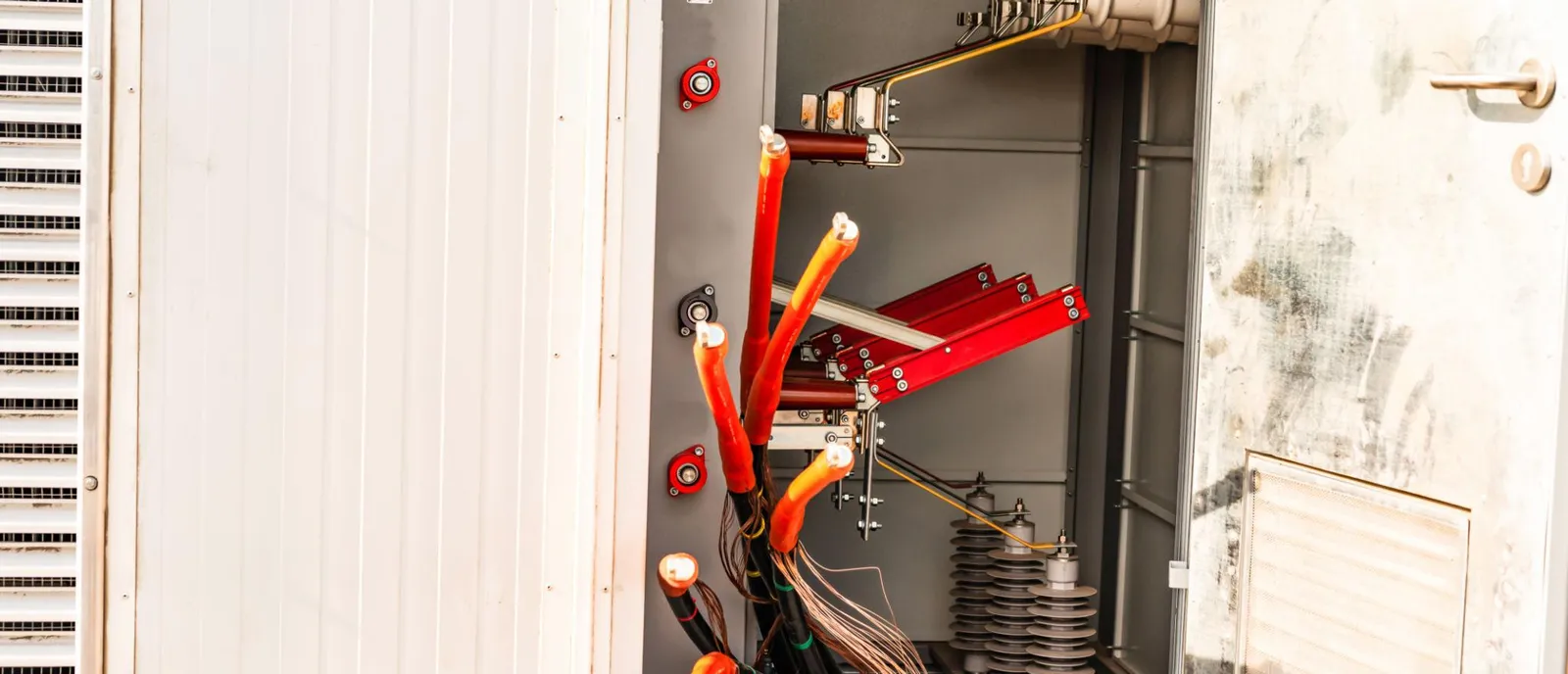
- Synchronising and paralleling with the grid
- Islanding scheme and load shedding
- Reverse power and export limits
- Protection coordination with the utility
- Power factor and harmonics control
- Captive metering at generation and consumption ends
- Integration with rooftop solar and batteries
- Energy management system and SCADA
Exporting surplus power, or wheeling it to other sites, needs connectivity and open access permission from the transmission or distribution licensee and approval of the state regulator.
Section 07
Captive Status, Open Access and Approvals
In India a captive generating plant is defined under the Electricity Act, 2003 and the Electricity Rules, 2005. Genuine captive users are exempt from the cross-subsidy surcharge and additional surcharge on open access, which often decides the economics.
Captive status is verified every year, so ownership and consumption must be planned and recorded from the start.
7.1Captive conditions (India)
| Condition | Requirement |
|---|---|
| Ownership | Captive users hold not less than 26 % of the ownership (equity with voting rights) of the plant or its special purpose vehicle |
| Consumption | Captive users consume not less than 51 % of the electricity generated, on an annual basis |
| Group captive / association | Each user's consumption must be in proportion to its share of ownership, within the variation allowed by the Rules |
| Verification | Compliance is checked annually by the designated authority; a shortfall can bring surcharges for the whole year |
7.2Typical approval path
- 1Steam and power study, captive structure and ownership plan
- 2Pollution control board consent to establish
- 3Environmental clearance where the fuel and size require it
- 4Boiler registration and inspection under the Boilers Act
- 5Electrical inspectorate approval for the installation
- 6Connectivity and open access applications, where exporting or wheeling
- 7Consent to operate and commissioning
This summary is for orientation; the Rules have been amended over time and states add their own procedures. Confirm the current text with the regulator or legal counsel before structuring a captive or group captive project.
Section 08
Turnkey EPC Delivery
BARREL can build a cogeneration plant under a single contract or coordinate the boiler, turbine and electrical packages, including tie-ins to a running factory with minimum shutdown.
Mechanical
4- Boiler or HRSG
- Turbine-generator or engine sets
- Fuel handling and storage
- Steam and condensate piping
Electrical and control
4- Generator switchgear and transformers
- Synchronising and islanding panels
- DCS / PLC and SCADA
- Cabling and earthing
Civil and utilities
4- Foundations and buildings
- Cooling towers and water treatment
- Chimney and emission monitoring
- Tie-ins to the existing plant
8.1Typical schedule
- Energy audit & balance 1–3 mo
- Design & approvals 3–6 mo
- Supply & build 9–24 mo
- Tie-in & commissioning 1–3 mo
Section 09
Operation and Maintenance
A captive plant must run when the factory runs. Planned maintenance aligned with production shutdowns and close watch on fuel and steam efficiency keep it reliable and economic.
- Shift operation of boilers, turbines and engines
- Boiler water chemistry and blowdown control
- Engine oil analysis and overhaul cycles
- Annual boiler inspection and statutory tests
- Steam trap and insulation surveys
- Heat rate and fuel-to-steam ratio tracking
- Captive consumption and ownership records
- Emission monitoring and compliance reports
- Spares and consumables planning
Section 10
Finance and Commercial Models
The value of a CHP plant lies in the difference between what the site pays today for grid power and boiler fuel and what it will pay for the cogeneration fuel and upkeep.
| Model | How it works |
|---|---|
| Owner-operated captive | Industry invests, owns and runs the plant |
| Group captive SPV | Several users hold equity in a common plant and buy its power |
| Build-own-operate (BOO) | A developer owns the plant and sells power and steam under a long-term agreement |
| Energy services (ESCO) | Savings shared between the user and the investor over the contract term |
| Lease or rental gensets | Short-term or standby capacity without capital outlay |
Paybacks of 3–6 years are common where the heat is fully used and grid tariffs are high, but results vary widely with fuel price, tariffs and running hours. Each case needs its own model.
Section 11
Lower-Carbon Cogeneration and Standards
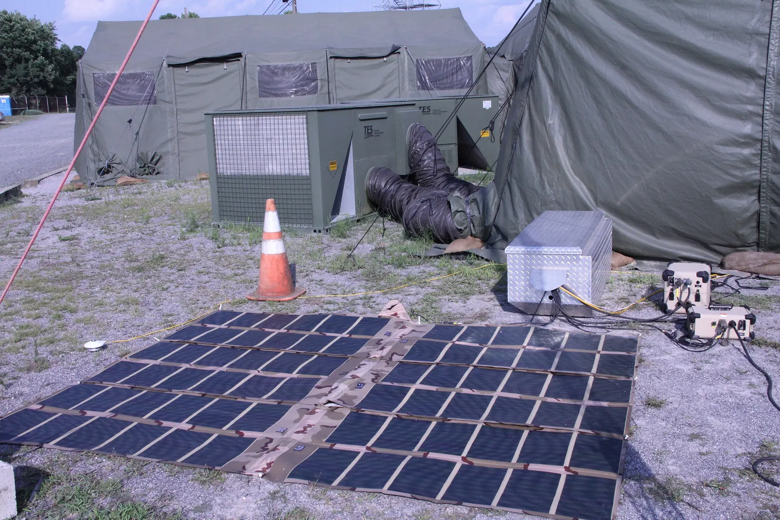
Existing and new CHP plants can move towards lower emissions by changing fuel and recovering more low-grade heat.
01
Biomass and biogas
Co-firing or full switch to agro-residue, pellets or biogas from effluent treatment.
02
Hybrid captive
CHP combined with solar, wind and batteries under captive or green open access arrangements.
03
Low-grade heat
ORC units and industrial heat pumps lift waste heat that was too cool to use before.
11.1Common standards and references
- Indian Boiler Regulations
- IS 2026 (transformers)
- ISO 8528
- ISO 3046
- ASME PTC 4
- ASME PTC 6
- BEE energy audit guidelines
- CPCB genset norms
Section 12
BARREL Services for Cogeneration and Captive Power
One partner from the first energy audit to decades of operation, backed by BARREL's network of consultants, manufacturers and contractors.
- Energy audit and steam-power balance
- Pre-feasibility and DPR
- Captive and group captive structuring support
- Open access and approvals support
- Boiler, turbine and genset sourcing
- Trigeneration and VAM design
- Waste-heat recovery studies
- Owner's engineer and lender's engineer
- Turnkey EPC / EPCM
- O&M and efficiency improvement
- Fuel switching and hybrid captive
- Acquisition due diligence
Project desk
Build your cogeneration or captive plant with BARREL
From the steam balance to reliable power and heat on site.
Planning a CHP or trigeneration plant, recovering waste heat, setting up a captive or group captive plant or upgrading gensets — tell us about your site's power and heat needs and we will respond with the next steps.
Project categories
- Steam turbine cogeneration
- Gas turbine CHP
- Gas engine CHP
- Trigeneration
- Waste-heat recovery
- Captive / group captive
- DG / GG sets