
- Sector engineering
- Complete power grid ecosystem
- Development · Engineering · EPC · O&M
Grid Infrastructure, Substations, Transmission Networks & Microgrids
From generation connectivity to the consumer — one connected network.
Generator switchyards and pooling substations, EHV / UHV transmission, grid substations, distribution networks, microgrids, smart grids and integrated power infrastructure. BARREL covers planning, development, engineering, manufacturing, procurement, construction, testing, commissioning, operation, maintenance, modernisation and trading across the whole electricity network.
- AC voltage range covered
- 415 V – 1,200 kV
- HVDC configurations
- ± 800 kV
- Business verticals
- 15
- BARREL grid divisions
- 12
- Questions answered
- 30
Understand the grid
Section 01
Grid infrastructure — the foundation of the power sector
Every power plant, renewable project, factory, railway, data centre, city and household depends on a reliable electrical network. Grid infrastructure connects generation with consumption: it evacuates power from generating stations, carries it over long distances, transforms it between voltage levels, distributes it to consumers and manages it through protection, control and communication systems.
It is much broader than substations and transmission lines: grid connectivity, evacuation, protection, automation, digital control, distribution, energy storage integration and microgrids are all part of it.
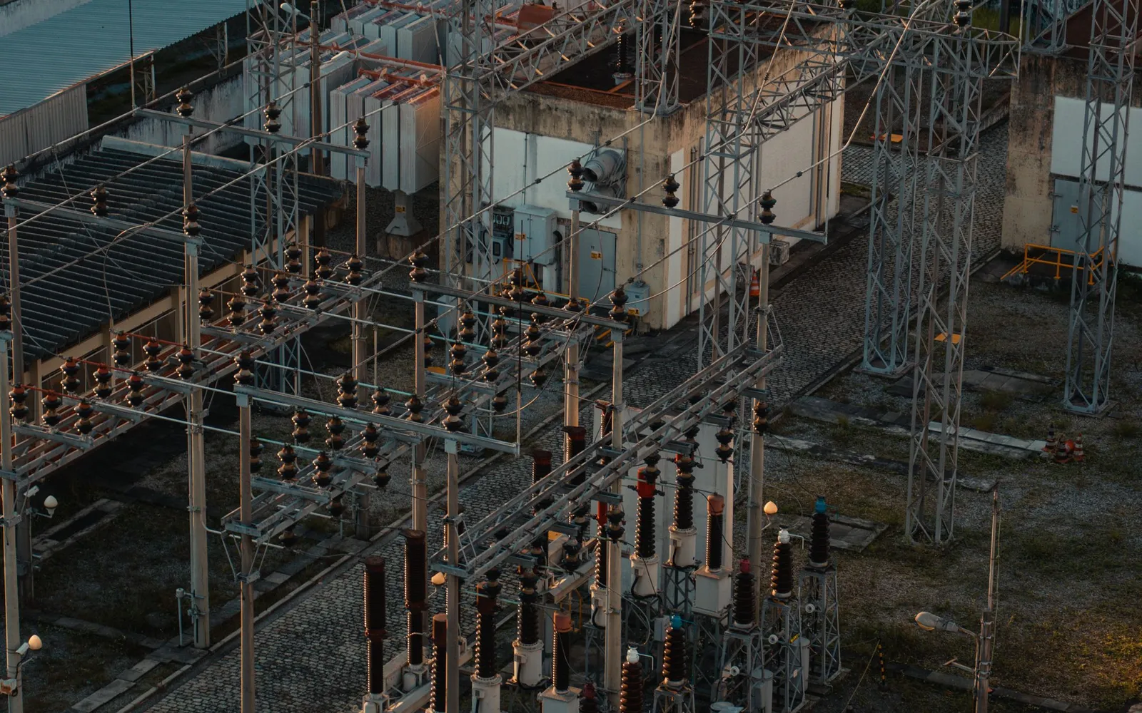
What grid infrastructure includes
The physical, electrical, mechanical, communication and control infrastructure to connect, transmit, transform, distribute, manage and consume power.
- Generation switchyards and power evacuation systems
- Renewable energy pooling substations
- Grid substations and switching stations
- Power transformers and reactors
- Transmission lines and towers
- Underground and submarine cables
- HVDC transmission systems
- Distribution substations and networks
- Switching and protection equipment
- Reactive power compensation systems
- Grid automation and digital substations
- Load dispatch and control centres
- Smart grids and microgrids
- Battery energy storage integration
- Industrial and captive power infrastructure
- Power quality and reliability systems
- Testing, inspection, maintenance and asset management
How the grid is changing
- Renewable integration
- Battery storage
- Electric mobility
- Distributed generation
- Smart grids
- Microgrids
- Digital substations
- HVDC transmission
- Artificial intelligence
BARREL grid infrastructure business scope
Fifteen verticals, covered across the sixteen sections of this guide.
| Business vertical | Main scope |
|---|---|
| Generation Connectivity | Generator switchyards, evacuation and grid interconnection |
| Pooling Substations | Solar, wind and hybrid renewable pooling infrastructure |
| Grid Substations | AIS, GIS, hybrid and EHV substations |
| Switching Stations | Line switching, sectionalising and bus arrangements |
| Transmission Lines | Overhead, underground and submarine transmission |
| HVDC Systems | High-voltage direct-current transmission |
| Distribution Infrastructure | Primary and secondary distribution networks |
| Microgrids | Grid-connected and islanded local power systems |
| Smart Grids | Intelligent monitoring, automation and control |
| Grid Modernisation | Upgradation, expansion and refurbishment |
| Protection & Automation | Relays, SCADA, SAS, communication and control |
| Power Quality | Reactive power, harmonic and voltage management |
| Energy Storage Integration | BESS, pumped storage and hybrid grid systems |
| Industrial Power Infrastructure | Captive substations, networks and power systems |
| Testing & O&M | Inspection, commissioning, maintenance and asset management |
BARREL positioning
One complete power infrastructure business — from generator terminals and pooling substations to EHV / UHV transmission, grid substations, distribution, microgrids and intelligent power management.
How this guide is arranged
Part 1Understand the grid
Part 2Network assets
Part 3Control & special networks
Part 4Build & deliver
Part 5Business & reference
Section 02
The complete electricity network and its voltage levels
Nine stages carry electricity from the generator to the consumer. Voltage is raised for transmission, then stepped down stage by stage — because higher voltage means lower current for the same power, and resistive losses fall with the square of the current.
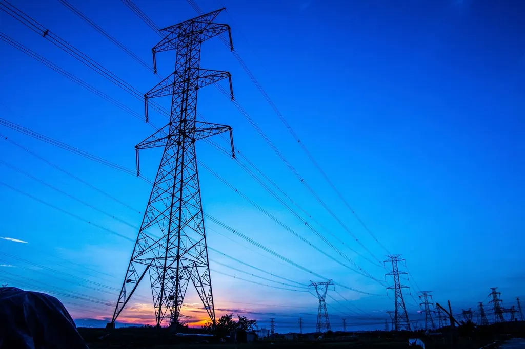
Generation to consumer at a glance
Swipe sideways to see the full diagram. Conceptual chain; numbers match the cards below. Voltages are typical Indian practice and vary by network.
The nine stages
- 01
Power generation
Solar, wind, hydro, thermal, nuclear and other generating stations produce electricity.
- 02
Generation switchyard
Generator output is connected to the network through transformers, circuit breakers and associated equipment.
- 03
Pooling substation
Power from several units or renewable projects is collected and stepped up for evacuation.
- 04
Transmission network
HV and EHV lines carry bulk power over long distances.
- 05
Grid substation
Power is transformed, switched, protected and routed through the interconnected grid.
- 06
Sub-transmission
Power is delivered towards regional and local distribution systems.
- 07
Distribution substation
Voltage is reduced to levels suitable for local distribution.
- 08
Distribution network
Electricity is supplied to industrial, commercial, institutional and residential consumers.
- 09
Consumer infrastructure
Final systems distribute power inside factories, buildings, campuses and facilities.
Grid classification by function
| Classification | Description |
|---|---|
| Generation network | Electrical system within and around generating stations |
| Evacuation network | Transfers generated electricity to pooling or grid substations |
| Pooling network | Collects power from multiple generators |
| Transmission network | Bulk power transmission over long distances |
| Sub-transmission network | Transfers power towards distribution areas |
| Distribution network | Supplies electricity to end consumers |
| Industrial network | Captive and dedicated industrial power infrastructure |
| Microgrid network | Localised, coordinated electrical network |
| Smart grid | Digitally monitored and controlled electricity network |
Indian AC voltage levels
- 415 VLVLow-voltage distribution
- 690 VLVIndustrial and equipment distribution
- 3.3 kVMVIndustrial power systems
- 6.6 kVMVIndustrial distribution and motors
- 11 kVMVPrimary distribution
- 22 kVMVDistribution and sub-transmission
- 33 kVMVDistribution, renewable collection and sub-transmission
- 66 kVHVSub-transmission
- 110 kVHVTransmission and sub-transmission in some systems
- 132 kVHVTransmission and grid substations
- 220 kVEHVEHV transmission
- 400 kVEHVEHV transmission
- 500 kV ACEHVTransmission in certain international systems
- 765 kVUHVUHV AC transmission
- 1,000–1,200 kVUHVSpecialised UHV development and applications
Global voltage master — nominal network voltage is not equipment voltage
A 400 kV network uses 420 kV-class equipment. Dashed tiles are maximum equipment classes (IEC 60038); the rest are nominal voltages. What counts as transmission differs by country — verify against the grid code.
11 kV
MV / sub-transmissionDistribution and industrial networks
13.2–13.8 kV
MVRegional distribution, industrial and generation
15–22 kV
MVRegional, railway, distribution
25 kV
MVRailway traction
30–34.5 kV
MV / sub-transmissionDistribution, renewable evacuation
45–60 kV
HVRegional and industrial systems
66 / 69 kV
HVSub-transmission
72.5 kV
Equipment classFor 66/69 kV systems
88–100 kV
HVRegional systems
110 / 115 kV
HVTransmission and sub-transmission
123 kV
Equipment classFor 110/115 kV systems
132 / 138 kV
HVTransmission
145 kV
Equipment classFor 132/138 kV systems
150–161 kV
HVRegional and North American transmission
187–200 kV
HVJapan, special applications
220 / 230 kV
HV / EHVMajor transmission
245 kV
Equipment classFor 220/230 kV systems
275 kV
EHVUK, Japan and others
300–345 kV
EHVRegional, China, Russia, North America
362 kV
Equipment classFor 345 kV systems
380 / 400 kV
EHVEurope, India and many grids
420 kV
Equipment classFor 400 kV systems
500 / 525 kV
EHVMajor global bulk transmission
550 kV
Equipment classFor 500/525 kV systems
600–700 kV
EHV / specialSpecial high-capacity systems
735 / 750 kV
EHVCanada, China, Russia
765 kV
EHVIndia, North America and others
800 kV
Equipment classFor 765 kV systems
1,000 / 1,100 kV
UHV ACChina and advanced UHV
1,200 kV
UHV researchDevelopment and experimental
Country examples
Representative, not exhaustive national inventories.
- India
- 66, 110, 132, 220, 400, 765 kV; 1,200 kV experimental
- USA
- 69, 115, 138, 161, 230, 345, 500, 765 kV
- Canada
- 69, 115, 138, 230, 315, 500, 735 kV
- China
- 110, 220, 330, 500, 750, 1,000 kV
- Japan
- 66, 77, 110, 132, 154, 187, 220, 275, 500 kV
- UK
- 132, 275, 400 kV
- Germany
- 110, 220, 380 kV
- France
- 63, 90, 225, 400 kV
- Russia
- 110, 220, 330, 500, 750 kV
- Brazil
- 69, 138, 230, 345, 440, 500, 750 kV
- South Africa
- 66, 132, 275, 400, 765 kV
- Australia
- 66, 110, 132, 220, 275, 330, 500 kV
- Gulf
- 110, 132, 220, 230, 380, 400 kV
- South Korea
- 154, 345, 765 kV
HVDC voltage levels
For long-distance bulk transfer, asynchronous interconnection and long underground or submarine cables. DC voltage is stated pole-to-ground or pole-to-pole — always record which.
- ± 100 kV
- ± 200 kV
- ± 320 kV
- ± 400 kV
- ± 500 kV
- ± 600 kV
- ± 800 kV
- Project-specific
Why voltage matters — and why voltage is not capacity
Current for a given power
I = P ÷ (√3 × V × pf)
Resistive loss
P_loss = 3 × I² × R
Three-phase apparent power
S = √3 × VLL × I
Three-phase active power
P = √3 × VLL × I × PF
Doubling the voltage halves the current and cuts the I²R loss to a quarter on the same conductor — the reason 400 kV and 765 kV corridors carry bulk power. But a 400 kV line has no single MW rating: transfer capability depends on conductor and bundle, circuits, thermal rating, stability limits, reactive power, length and ambient conditions; a 765/400 kV substation is a voltage ratio, and its MVA depends on the transformers installed. For a first screening of a real line use the line estimator.
Technologies at a glance — which one does what
| Technology | Main purpose | Typical application |
|---|---|---|
| Overhead AC line | Bulk power transfer | Regional and national grids |
| Underground AC cable | Constrained corridors | Cities, industrial areas |
| Submarine AC cable | Short-to-medium subsea links | Offshore wind, islands |
| HVDC overhead line | Long-distance bulk transfer | Inter-regional transfer |
| HVDC cable | DC transfer, underground or subsea | Interconnectors, offshore wind |
| AIS substation | Switching and transformation | Open-land sites |
| GIS substation | Compact switching | Urban and constrained sites |
| Hybrid substation | Mixed AIS/GIS | Space and cost optimisation |
| Digital substation | Digital control and protection | New and upgraded stations |
| HVDC converter station | AC/DC conversion | HVDC terminals |
| STATCOM / SVC | Dynamic reactive support | Voltage and stability control |
For browsing — not a substitute for project-specific design. Voltage lists here are a starting taxonomy, validated against the grid code and the utility's specification before design.
Section 03
Grid substations — complete engineering and infrastructure
A grid substation receives, transforms, switches, protects, controls and distributes power. It is the connection point between generation, transmission, sub-transmission and distribution.
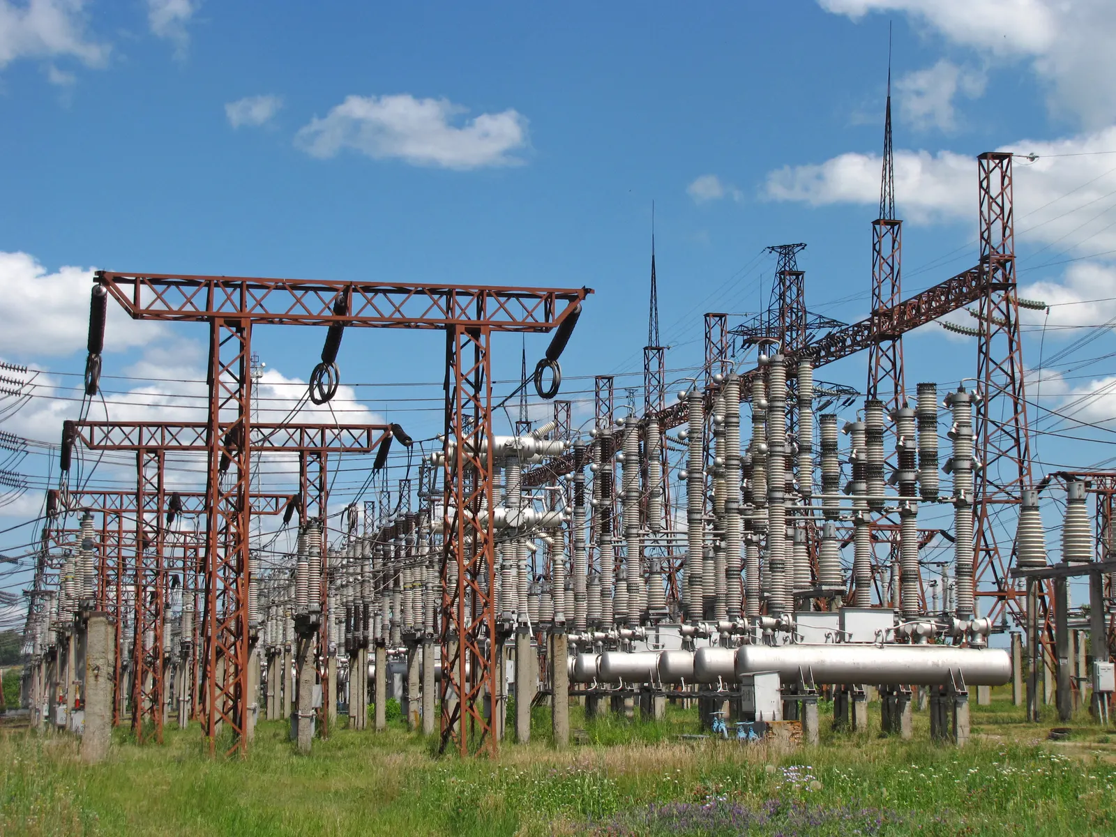
Types of substation
AStep-up substation
Raises generator output voltage to a transmission voltage.
Typical infrastructure
- Generator transformers
- Generator circuit breakers, where applicable
- Isolated phase bus or bus ducts
- HV switchyard
- Circuit breakers and isolators
- CTs and VTs
- Surge arresters
- Protection and control
- Metering and communication
BStep-down substation
Reduces transmission voltage for sub-transmission or distribution. Actual combinations follow the local network.
Examples
- 400/220 kV
- 220/132 kV
- 132/66 kV
- 132/33 kV
- 66/33 kV
- 33/11 kV
CGrid switching station
Switching and network interconnection without necessarily transforming voltage.
Applications
- Transmission line switching
- Grid sectionalising
- Busbar interconnection
- Network redundancy
- Power flow management
- Fault isolation
- System reliability
DConverter substation
Used in HVDC and other power-electronic transmission systems.
May include
- AC switchyard
- Converter transformers
- Converter valves
- Smoothing reactors
- AC and DC filters
- DC switchyard
- Control and protection
- Cooling systems
- Electrode line, where applicable
EDistribution substation
Transforms electricity to medium or low voltage for distribution.
Examples
- 33/11 kV
- 22/11 kV
- 11/0.433 kV
- Other utility-specific combinations
FIndustrial and captive substation
Dedicated substations for large industrial and infrastructure loads.
For
- Steel, cement and aluminium plants
- Chemical plants and refineries
- Mines
- Data centres
- Manufacturing complexes
- Railways and metro
- Ports and airports
Substation technologies
- 01
Air Insulated Substation (AIS)
Outdoor equipment with air as the principal insulation medium. Lowest equipment cost; needs the most land.
- 02
Gas Insulated Substation (GIS)
Compact metal-enclosed switchgear using an insulating gas or an approved alternative medium. For cities, caverns and tight sites.
- 03
Hybrid substation
AIS and GIS equipment combined to suit space, reliability and project requirements.
- 04
Mobile substation
Transportable substation for temporary supply, emergencies and maintenance support.
Busbar configurations
Selected for reliability, flexibility, maintainability, fault levels, land and lifecycle cost — not by voltage alone.
- Single busbar
- Single busbar with bus section
- Single busbar with bus coupler
- Main and transfer bus
- Double busbar
- Double busbar with double breaker
- One-and-a-half breaker scheme
- Ring bus scheme
- Mesh bus scheme
- Breaker-and-a-half arrangement
- Specialised GIS bus configurations
| Arrangement | Reliability | Flexibility | Land / cost | Typical use |
|---|---|---|---|---|
| Single busbar | Low | Low | Lowest | Small distribution and industrial substations |
| Main and transfer bus | Medium | Breaker maintenance without outage | Moderate | 132 kV and below, older utility practice |
| Double busbar | High | Circuits move between buses | Higher | 220 kV grid substations |
| One-and-a-half breaker | Very high | Any breaker out without loss of supply | High | 400 kV and 765 kV EHV substations |
| Ring / mesh bus | High | Good for few circuits | Moderate | Compact EHV and switching stations |
Qualitative comparison. The scheme for each voltage level follows the utility's specification and the CEA construction standards.
Main equipment in a grid substation
| Equipment | Function |
|---|---|
| Power transformer | Voltage transformation |
| Auto transformer | Transformation between interconnected voltage levels |
| Circuit breaker | Switching and fault interruption |
| Isolator / disconnector | Electrical isolation |
| Earth switch | Grounding isolated equipment |
| Current transformer (CT) | Current measurement and protection |
| Voltage transformer (VT / PT / CVT) | Voltage measurement and protection |
| Surge arrester | Overvoltage protection |
| Busbar | Common electrical connection |
| Insulators | Electrical insulation and mechanical support |
| Shunt reactor | Reactive power absorption |
| Shunt capacitor | Reactive power compensation |
| Series capacitor | Transmission impedance compensation |
| Wave trap | Power-line carrier communication |
| Coupling capacitor | Communication and measurement interface |
| Neutral grounding equipment | System grounding and fault-current control |
| Protection relay | Fault detection and trip logic |
| Battery and charger | DC auxiliary supply |
| AC distribution board | Auxiliary AC supply |
| DC distribution board | Protection and control supply |
| SCADA / SAS | Monitoring, control and automation |
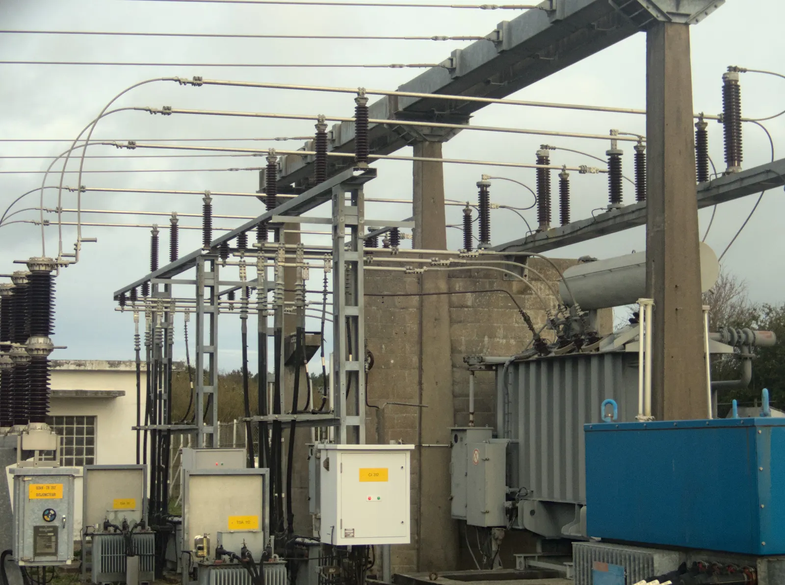
Auxiliary systems
17- AC auxiliary power system
- DC battery system
- Battery chargers
- UPS system
- Lighting systems
- Fire detection and suppression
- HVAC and ventilation
- Earthing and bonding
- Lightning protection
- Cable trenches and ducts
- Control and relay panels
- Communication equipment
- Security and access control
- CCTV and perimeter protection
- Water supply and drainage
- Oil containment and drainage
- Emergency facilities
Substation engineering services
- Site feasibility
- Land and layout planning
- Electrical single-line diagrams
- General arrangement drawings
- Substation layout
- Busbar design
- Equipment specifications
- Transformer sizing
- Fault-level calculations
- Short-circuit studies
- Load-flow studies
- Insulation coordination
- Earthing design
- Lightning protection design
- Protection coordination
- Cable sizing
- Illumination design
- Civil and structural engineering
- Fire protection engineering
- SCADA and automation engineering
- Communication engineering
- Testing and commissioning
Section 04
Generation connectivity — pooling substations, switchyards and evacuation
Two ways a power plant meets the grid. A generation switchyard connects one station's output to the network; a pooling substation collects power from several plants or renewable projects through common busbars and transformers and evacuates it on shared lines — so each project does not need its own long line.
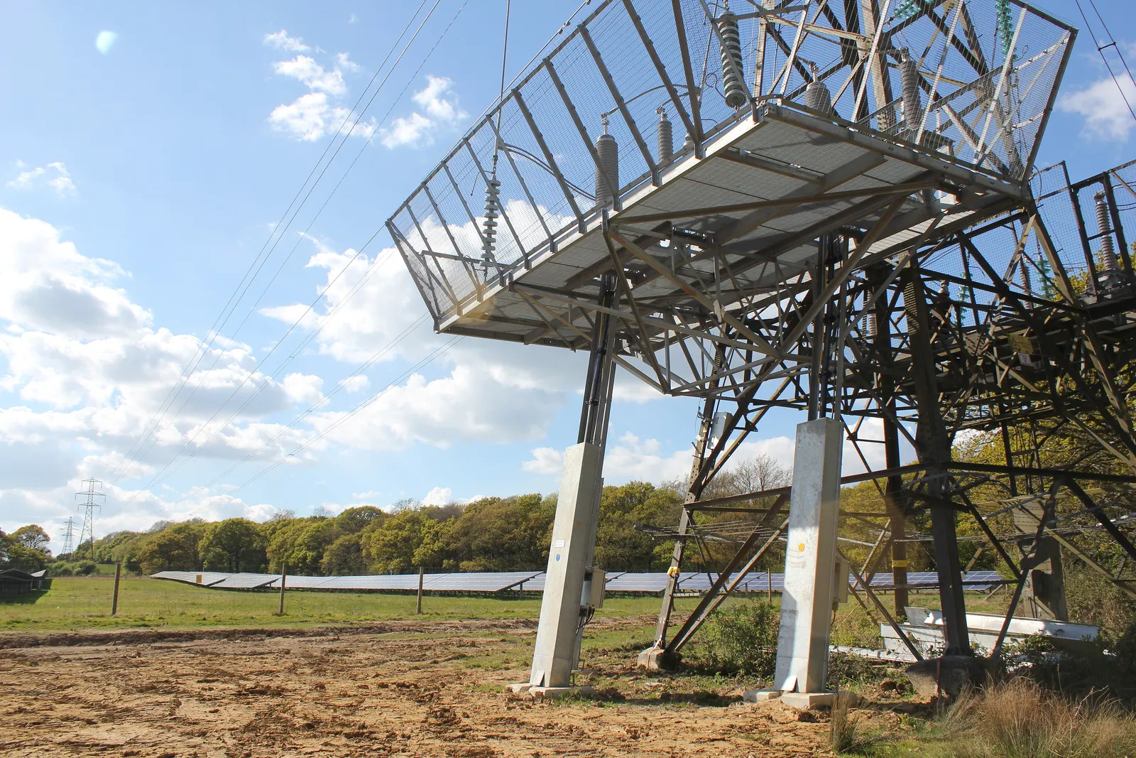
How a pooling substation is arranged
Example: solar and wind blocks on 33 kV collection feeders, stepped up to 220 kV for evacuation.
Swipe sideways to see the full diagram. Conceptual single-line diagram — not a design drawing. Bus scheme, transformer count and reactors follow grid studies.
Types of pooling substation
9- Solar power pooling substation
- Wind power pooling substation
- Hybrid solar-wind pooling substation
- Renewable energy park pooling substation
- Battery energy storage pooling substation
- Pumped storage grid connection substation
- Independent power producer pooling station
- Industrial captive power pooling station
- Multi-developer renewable energy pooling station
| Collection voltage | Evacuation voltage examples |
|---|---|
| 11 kV | 33 kV / 66 kV |
| 22 kV | 66 kV / 132 kV |
| 33 kV | 132 kV / 220 kV |
| 66 kV | 132 kV / 220 kV |
| 132 kV | 220 kV / 400 kV |
| 220 kV | 400 kV / 765 kV |
Indicative engineering combinations, not universal prescribed pairings.
Renewable energy collection network
Solar power collection
- 1Solar inverter output
- 2Inverter transformer
- 333 kV or project-specific collection feeder
- 4Feeder protection
- 5Underground or overhead collection network
- 6Pooling substation
Wind power collection
- 1Wind turbine generator
- 2Turbine converter
- 3Wind turbine transformer
- 4Medium-voltage collection network
- 5Feeder protection
- 6Pooling substation
Hybrid collection
- 1Solar generation
- 2Wind generation
- 3BESS
- 4Common collection system
- 5Plant controller
- 6Pooling substation
- 7Grid evacuation network
Pooling substation components
- Incoming feeder bays
- Collection busbars
- Main power transformers
- Interconnecting transformers
- Bus couplers
- Bus section breakers
- Outgoing transmission line bays
- Circuit breakers
- Isolators
- CTs and CVTs
- Surge arresters
- Shunt reactors
- Capacitor banks
- Harmonic filters, where required
- Protection and control panels
- Metering systems
- SCADA and communication
- Auxiliary power systems
- Fire protection systems
Generation switchyards
The critical interface between the plant and the grid.
Types of generation switchyard
10- Thermal power plant
- Hydro power plant
- Nuclear power plant
- Solar power plant
- Wind power plant
- Biomass power plant
- Waste-to-energy
- Pumped storage power plant
- Battery energy storage grid connection
- Captive power plant
Main components
17- Generator transformers
- Generator circuit breakers
- Isolated phase bus systems
- Bus ducts
- Generator protection systems
- HV circuit breakers
- Isolators
- Current transformers
- Voltage transformers
- Surge arresters
- Busbars
- Power transformers
- Earthing systems
- Protection and control panels
- Metering systems
- Synchronisation systems
- SCADA and communication
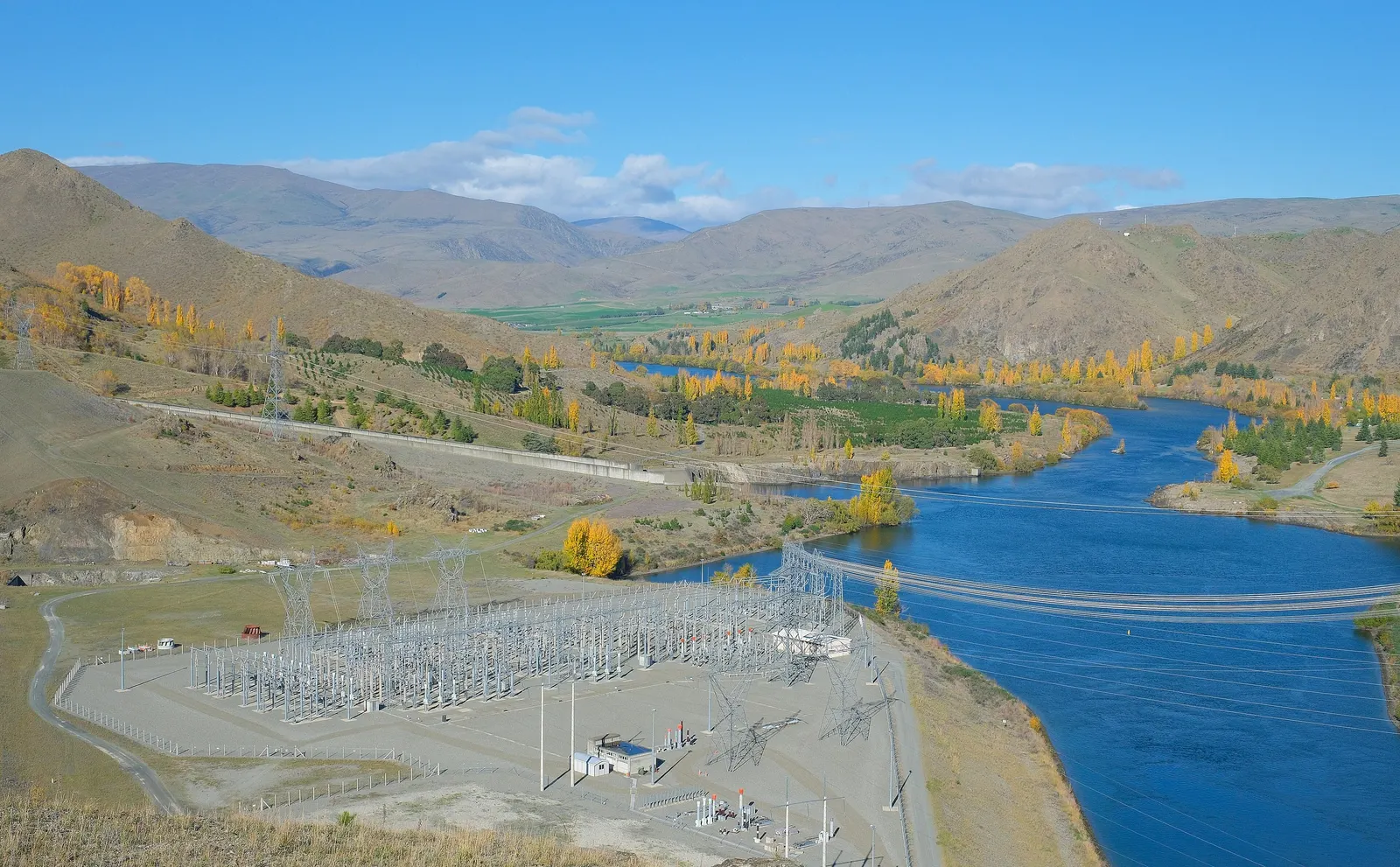
Power evacuation — generator terminals to the grid connection point
- 1Generator terminal systems
- 2Generator step-up transformers
- 3Plant switchyard
- 4Evacuation transmission line
- 5Renewable pooling station, where applicable
- 6Dedicated transmission line
- 7Grid interconnection bay
- 8Grid substation modifications
- 9Communication and protection systems
- 10Metering and grid compliance
Generation connectivity services
- Pooling substation feasibility
- Land identification
- Grid connectivity coordination
- Detailed project report
- Electrical system design
- Transformer procurement
- AIS / GIS equipment procurement
- 33 kV collection systems
- 66 kV collection systems
- 132 kV pooling substations
- 220 kV pooling substations
- 400 kV pooling substations
- 765 kV renewable evacuation infrastructure
- Transmission line construction
- Bay extension works
- Testing and commissioning
- Grid compliance coordination
- O&M services
BARREL opportunity
A complete Generation-to-Grid Connectivity Package for solar, wind, hydro, thermal, nuclear, biomass, battery storage and hybrid projects — one owner for the interface between the plant and the network.
Section 05
Transmission lines — overhead, underground and submarine, 11 kV to 765 kV and UHV
Transmission lines connect geographically separated generation with demand. Route, tower, conductor and foundation choices decide cost, losses and reliability for decades.
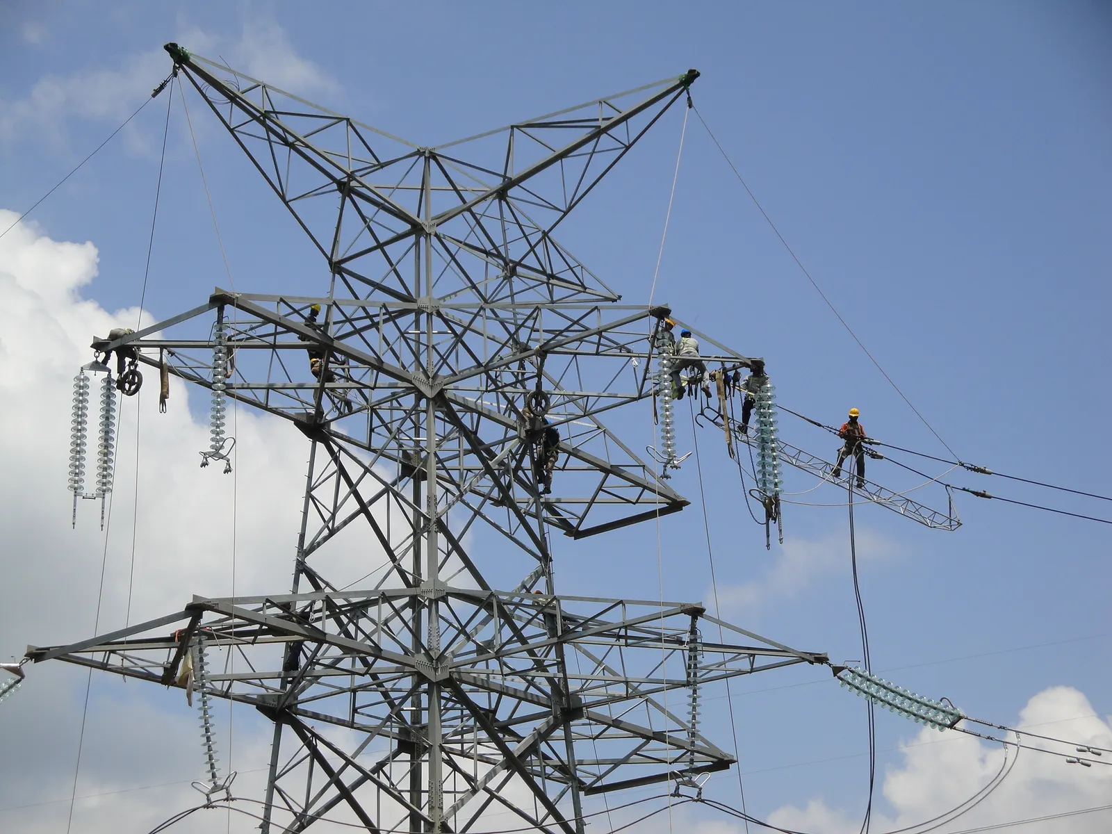
Why transmission matters
- Transfers bulk electricity over long distances
- Connects generation to load centres
- Integrates solar, wind, hydro, nuclear and thermal
- Enables cross-border and inter-regional exchange
- Improves stability, reliability and resilience
- Serves industrial corridors, cities, railways, ports and data centres
Three ways to carry power — explore each
Transmission · 01
Overhead Lines
Bulk power over long distances on towers and poles.
Single, double and multi-circuit lines with bundled conductors, lattice towers, monopoles and complete line hardware — from 11 kV to 765 kV and 1,000 / 1,100 kV UHV AC.
By voltage
- 11, 22, 33 kV
- 66 kV
- 110/115 kV
- 132/138 kV
- 154/161 kV
- 220/230 kV
- 275 kV
- 330/345 kV
- 380/400 kV
- 500/525 kV
- 735/750 kV
- 765 kV
- 1,000/1,100 kV UHV
By circuit
- Single, double, triple, quadruple circuit
- Multi-voltage towers
- Compact lines
- Shared corridors
- Reconductoring and uprating
By tower
- Lattice steel
- Monopole and tubular pole
- H-frame and portal
- Guyed and self-supporting
- Suspension, tension, dead-end
- Transposition
- River, rail and highway crossing
- Long-span and terminal
By terrain
- Plain and agricultural
- Forest
- Hilly and mountainous
- Desert and coastal
- Wetland and river crossing
- Urban corridors
- Snow, ice, seismic, landslide zones
Conductors
- ACSR, AAAC, AAC, ACAR, AACSR
- ACSS
- ACCC and ACCR
- HTLS
- Carbon-core and gap-type
- Thermal-resistant aluminium
- Twin to eight-bundle and UHV bundles
Insulation & accessories
- Porcelain, toughened glass, composite
- Long-rod, suspension and tension strings
- Earthwire, OPGW, ADSS
- Spacer and Stockbridge dampers
- Corona and grading rings
- Clamps, joints, repair sleeves
- Bird diverters, anti-climb, aviation markers
Transmission · 02
Underground Cables
Transmission where overhead lines cannot go.
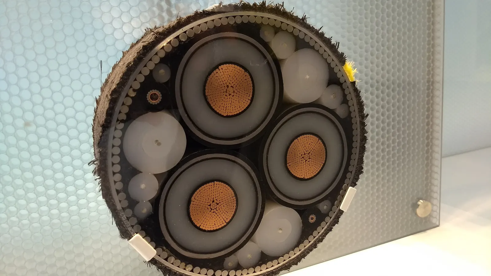
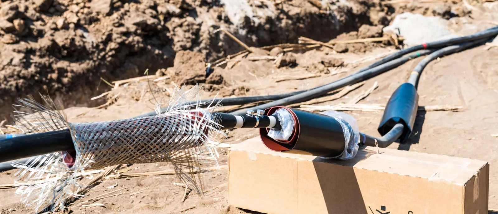
HV and EHV cables in cities, industrial areas and constrained corridors — direct-buried, in ducts or in tunnels, with thermal management and condition monitoring.
Voltage families
- 11–33 kV
- 66–132 kV
- 145–220 kV
- 245–400 kV
- 500–525 kV
- HVDC cables
Construction
- XLPE and EPR
- Oil-filled
- Mass-impregnated
- Pipe-type
- Single- and three-core
- Copper and aluminium conductors
- Cross-bonded systems
Accessories
- Straight-through and transition joints
- Outdoor, GIS and transformer terminations
- Link boxes and sheath voltage limiters
- Earthing and bonding
- Cable cleats
Infrastructure & monitoring
- Ducts, trenches, tunnels
- Fire barriers
- Distributed temperature sensing
- Partial discharge monitoring
Transmission · 03
Submarine Transmission
Power across the sea.
Subsea AC and HVDC links connect offshore wind, islands and neighbouring grids — with specialist marine partners for laying, burial and protection.
Systems
- Offshore wind export cables
- Inter-array cables
- AC and HVDC export
- Subsea interconnectors
- Island connections
- Floating wind cable systems
Infrastructure
- Cable protection
- Burial and trenching
- Landfall and transition joints
- Offshore converter platforms
- Offshore GIS substations
Transmission tower types
- 01
Suspension tower
Carries conductors along relatively straight sections of the route.
- 02
Angle tower
Takes the extra load where the line changes direction.
- 03
Terminal tower
Dead-ends the line at its termination and substation entry.
- 04
Special crossing tower
Tall or heavy towers for river, railway, highway and other major crossings.
Conductors
| Conductor | Full name | Where it fits |
|---|---|---|
| ACSR | Aluminium Conductor Steel Reinforced | The standard workhorse for most EHV lines |
| AAAC | All Aluminium Alloy Conductor | Lighter, corrosion-resistant; coastal and distribution lines |
| AAC | All Aluminium Conductor | Short spans, urban distribution |
| ACAR | Aluminium Conductor Alloy Reinforced | Better strength-to-weight than AAC |
| HTLS | High Temperature Low Sag | Reconductoring to raise capacity on existing towers |
| ACCC | Aluminium Conductor Composite Core | HTLS family; composite core, low sag |
| ACSS | Aluminium Conductor Steel Supported | HTLS family; annealed aluminium, high temperature |
Conductor selection depends on
- Current-carrying capacity
- Voltage level
- Electrical losses
- Temperature limits
- Sag and tension
- Wind and ice loading
- Corona performance
- Short-circuit withstand
- Mechanical strength
- Lifecycle cost
Transmission line engineering
Route engineering
11- Route alignment
- Reconnaissance survey
- Topographical survey
- Drone survey
- LiDAR survey
- GIS mapping
- Right-of-way assessment
- Forest and environmental assessment
- Railway and highway crossings
- River crossings
- Land and access planning
Electrical engineering
12- Line parameters
- Load flow
- Thermal rating
- Voltage drop
- Power transfer capability
- Corona and radio interference
- Insulation coordination
- Lightning performance
- Shielding angle
- Earthing
- Sag and tension
- Conductor selection
Mechanical and civil engineering
10- Tower spotting
- Tower design
- Foundation design
- Soil investigation
- Structural analysis
- Tower fabrication
- Tower erection
- Conductor stringing
- Tensioning
- OPGW installation
Digital engineering
7- PLS-CADD, PLS-TOWER, PLS-POLE
- LiDAR and drone surveys
- 3D terrain models
- Digital twins
- AI defect detection
- Satellite inspection
- Predictive analytics
Construction sequence
- 1Survey and route marking
- 2Land and right-of-way coordination
- 3Foundation excavation
- 4Reinforcement and concreting
- 5Tower fabrication and galvanising
- 6Tower transportation
- 7Tower erection
- 8Insulator installation
- 9Conductor stringing
- 10Earth wire stringing
- 11OPGW installation
- 12Jointing and termination
- 13Sagging and clipping
- 14Testing and inspection
- 15Pre-commissioning
- 16Charging and energisation
What comes next in transmission
- 1,000 / 1,100 kV UHV AC
- ±800 kV and higher UHVDC
- Multi-terminal HVDC grids
- HVDC circuit breakers
- Hybrid AC/DC networks
- Superconducting cables
- HTLS and composite-core conductors
- Dynamic line rating
- Compact narrow-base towers
- EHV cable tunnels
- Floating offshore wind transmission
- Digital substations
- Optical CT / VT sensing
- SF₆-free switchgear
- AI grid monitoring
- Autonomous drone inspection
- Digital twins
- Wide-area monitoring
- Grid-enhancing technologies
- Grid-forming power electronics
Section 06
HVDC, FACTS, power quality and grid stability
HVDC moves large blocks of power over long distances and through long cables, connects asynchronous grids and gives controllable power flow. FACTS devices and reactive compensation add control and stability to AC networks — increasingly needed with high renewable penetration, power-electronic loads and long lines.
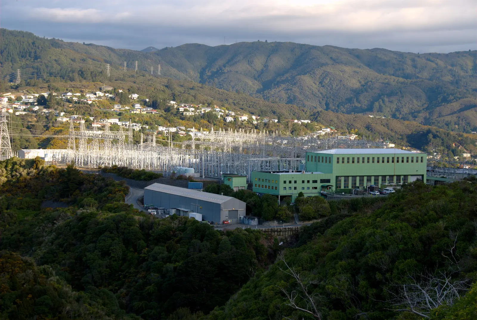
HVDC configurations
- Monopolar
- Bipolar
- Homopolar
- Back-to-back
- Multi-terminal
- Voltage Source Converter (VSC)
- Line Commutated Converter (LCC)
| LCC (thyristor) | VSC (IGBT) | |
|---|---|---|
| Typical use | Very large long-distance bulk links | Offshore wind, cables, weak grids, multi-terminal |
| Reactive power | Consumes it — needs filters and compensation | Controls it independently |
| Black start / weak grid | Needs a strong AC grid | Can support or energise weak grids |
| Footprint | Larger (filters) | Smaller |
| Power reversal | By reversing voltage polarity | By reversing current |
Main HVDC equipment
14- Converter transformers
- Converter valves
- Thyristor valves
- IGBT-based converter systems
- Smoothing reactors
- AC filters
- DC filters, where required
- DC switchyard
- AC switchyard
- Converter control and protection
- Cooling systems
- Electrode systems
- DC cables or overhead lines
- Communication systems
HVDC applications
8- Long-distance bulk power
- Offshore wind connections
- Inter-regional transfer
- Cross-border interconnections
- Asynchronous grid connections
- Underground cable transmission
- Submarine transmission
- Renewable integration
Flexible AC Transmission Systems (FACTS)
- 01
SVC
Static Var Compensator — thyristor-switched reactors and capacitors for fast voltage support.
- 02
STATCOM
Static Synchronous Compensator — converter-based dynamic reactive power, strong at low voltage.
- 03
TCSC
Thyristor Controlled Series Capacitor — varies line impedance to steer power flow and damp oscillations.
- 04
SSSC
Static Synchronous Series Compensator — injects a controllable series voltage.
- 05
UPFC
Unified Power Flow Controller — combined shunt and series control of voltage, impedance and angle.
- 06
Series and shunt compensation
Fixed capacitors and reactors that extend transfer capability and hold the voltage profile.
Reactive power compensation
Manages voltage profiles, reactive power flows, stability and network performance.
- Shunt capacitor banks
- Shunt reactors
- Series capacitors
- Synchronous condensers
- Static Var Compensators
- STATCOM
- Dynamic voltage support
- Power factor correction
- Harmonic filtering
Power quality — problem, cause and remedy
| Problem | Typical cause | Typical remedy |
|---|---|---|
| Harmonic distortion | VFDs, rectifiers, arc furnaces, inverters | Passive / active filters, detuned banks |
| Low power factor | Induction motors, lightly loaded transformers | APFC panels, capacitor banks, STATCOM |
| Voltage sag / swell | Faults, large motor starts, switching | DVR, UPS, STATCOM, network strengthening |
| Flicker | Arc furnaces, welders, fluctuating loads | SVC / STATCOM, stronger supply point |
| Overvoltage on light load | Long EHV lines charging the network | Shunt reactors, SVC |
Power quality parameters
13- Voltage regulation
- Voltage fluctuations
- Voltage unbalance
- Frequency variation
- Harmonic distortion
- Interharmonics
- Flicker
- Power factor
- Transient overvoltage
- Voltage sag
- Voltage swell
- Neutral current
- Electrical noise
Power quality equipment
12- Active harmonic filters
- Passive harmonic filters
- Detuned capacitor banks
- APFC panels
- SVC
- STATCOM
- Dynamic Voltage Restorer
- UPS
- Voltage regulators
- Automatic voltage control
- Power conditioners
- Synchronous condensers
Reliability and resilience
14- N-1 contingency planning
- Network redundancy
- Bus sectionalising
- Transformer redundancy
- Alternate transmission paths
- Emergency restoration
- Black start capability
- Grid restoration planning
- Fault isolation
- Load shedding
- Under-frequency load shedding
- System protection schemes
- Disaster resilience
- Spare equipment management
Section 07
Grid distribution infrastructure
Distribution delivers electricity from transmission and sub-transmission networks to consumers — substations, feeders, transformers, poles, cables, switching, metering and connections.
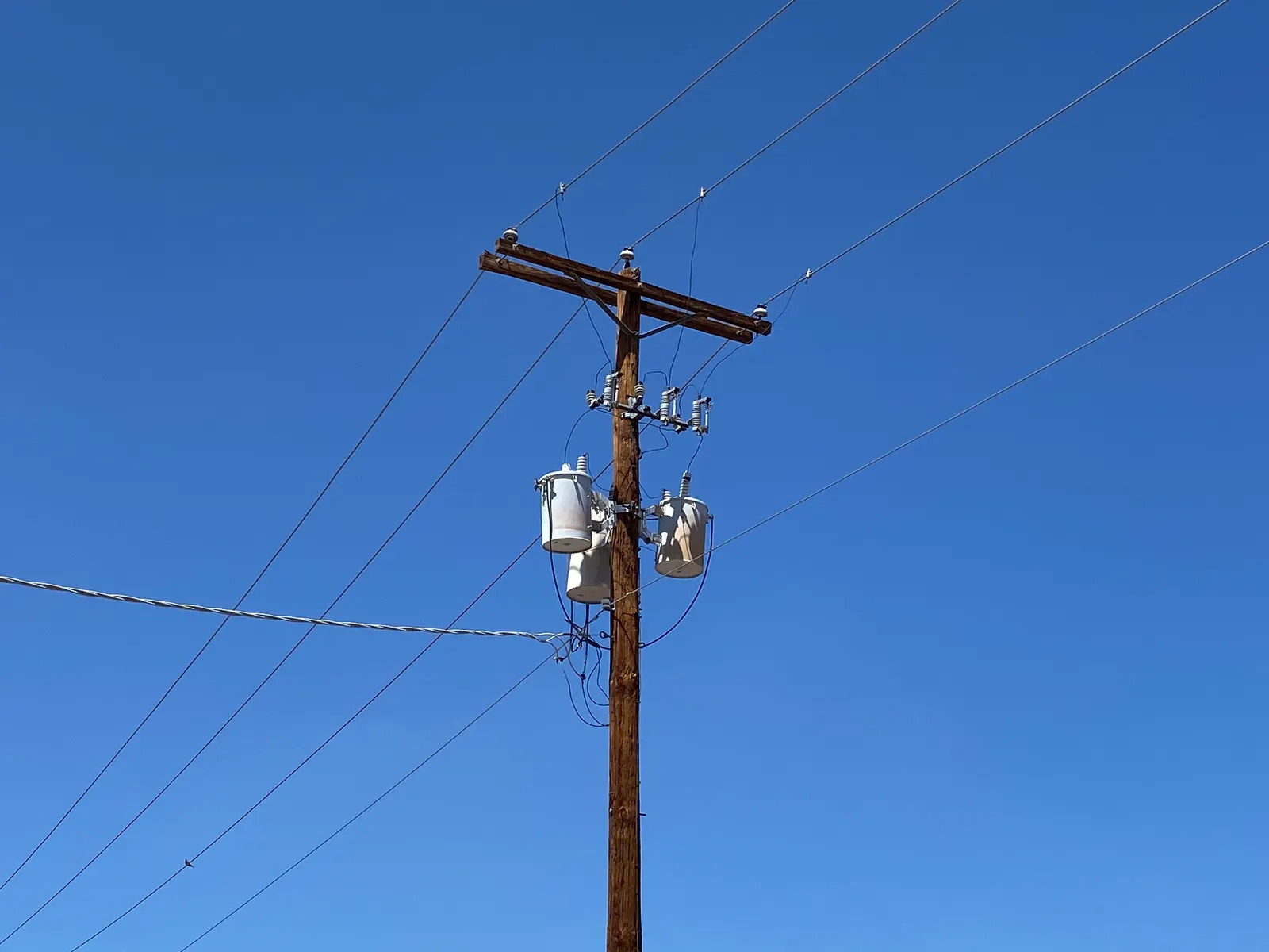
Primary distribution — 33 / 22 / 11 kV
8- Primary substations
- Distribution feeders
- Ring Main Units (RMUs)
- Sectionalising equipment
- Vacuum circuit breakers (VCBs)
- Distribution protection
- Feeder automation
- Underground and overhead cables
Secondary distribution — 415 V / 230 V
9- Distribution transformers
- LT distribution boards
- LT panels
- Distribution boxes
- Feeder pillars
- Service cables
- Metering systems
- Consumer connections
- Earthing and safety
Network configurations
10- Radial
- Ring-main
- Interconnected
- Underground
- Overhead
- Compact
- Urban
- Rural
- Industrial captive
- Campus
Distribution transformers
9- Pole-mounted
- Plinth-mounted
- Indoor
- Outdoor
- Oil-immersed
- Dry-type
- Cast-resin
- Hermetically sealed
- Special industrial
Distribution modernisation
12- Feeder segregation
- Distribution automation
- Smart meters
- Advanced Metering Infrastructure
- Distribution SCADA
- GIS network mapping
- Automated fault detection
- FLISR — fault location, isolation and service restoration
- Network loss reduction
- Transformer monitoring
- Voltage optimisation
- Power quality monitoring
BARREL engineering principle
Most technical losses and most outages a consumer sees happen in distribution. Feeder segregation, automation, metering and FLISR pay back fastest where loss and reliability data are measured first.
More on the energy distribution page.
Section 08
Microgrids, energy storage and renewable integration
A microgrid coordinates distributed energy resources, storage and loads within a defined electrical boundary. It can run connected to the utility grid or, if designed for it, on its own in island mode — a controllable network with generation, storage, distribution, protection, communication and energy management.
At grid scale, storage supports renewable integration, peak management, frequency response, voltage support, resilience and balancing.
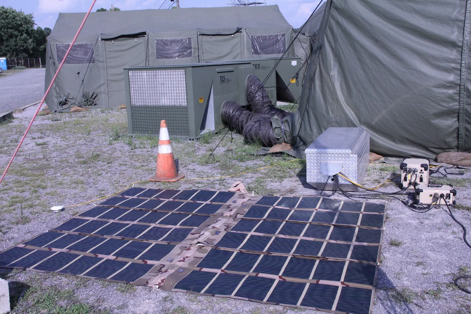
Microgrid architecture
Swipe sideways to see the full diagram. Conceptual microgrid. Opening the PCC breaker islands the microgrid; the grid-forming battery holds voltage and frequency.
- Local electricity generation
- Renewable energy sources
- Battery energy storage
- Backup generation
- Local electrical distribution
- Loads and consumers
- Protection and switching
- Microgrid controller
- Energy Management System (EMS)
- Grid interconnection, where applicable
Types of microgrid
AGrid-connected microgrid
Imports or exports with the utility grid, subject to connection agreements and permissions.
- Industrial facilities
- Commercial complexes
- Universities
- Hospitals
- Airports
- Data centres
- Business parks
- Residential townships
BIslanded microgrid
Runs independently of the main grid.
- Remote villages
- Islands
- Mining sites
- Remote industry
- Defence installations
- Disaster-response facilities
- Off-grid communities
CHybrid renewable microgrid
Several renewable and conventional sources with storage.
- Solar PV
- Wind power
- Battery storage
- Diesel or gas backup, where required
- Grid connection, if available
- Smart controller
DIndustrial microgrid
A dedicated network for a factory, industrial park or manufacturing complex.
- Steel and cement plants
- Chemical industries
- Refineries
- Mining
- Manufacturing clusters
- Warehouses and logistics parks
ECommercial and institutional
Resilient supply for critical and high-value facilities.
- Hospitals
- Universities
- IT parks
- Data centres
- Hotels
- Airports
- Shopping centres
- Government facilities
FCommunity microgrid
Serves several buildings, households or community facilities.
- Rural electrification
- Remote settlements
- Community solar
- Local energy cooperatives
- Public infrastructure
- Disaster-resilient communities
GMilitary and defence microgrid
Reliable power for strategic and remote sites.
- Defence bases
- Military camps
- Strategic installations
- Border infrastructure
- Remote communications
- Emergency facilities
- Rural microgrids
- Industrial microgrids
- Commercial microgrids
- Hospital microgrids
- Data centre microgrids
- University microgrids
- Airport microgrids
- Port microgrids
- Mining microgrids
- Island microgrids
- Defence microgrids
- Railway microgrids
- EV charging microgrids
- Renewable microgrids
- Hydrogen-based microgrids
Energy sources
13- Solar PV
- Wind power
- Battery storage
- Small hydro
- Biomass
- Hydrogen fuel cells
- Biogas generators
- Small gas turbines
- Diesel generator sets
- Natural gas engines
- Combined heat and power
- Waste-to-energy
- Vehicle-to-grid, where suitable
Electrical infrastructure
19- Solar PV arrays
- Wind turbines
- Generators
- Battery energy storage systems
- Power conversion systems
- Bidirectional inverters
- Transformers
- MV switchgear
- LV switchgear
- Ring Main Units
- Distribution transformers
- Protection relays
- Synchronising panels
- Grid-interconnection switchgear
- Automatic transfer systems
- Earthing systems
- Metering systems
- Power quality systems
- Microgrid control systems
Microgrid controller and operating modes
- Renewable generation forecasting
- Load forecasting
- Battery charge / discharge scheduling
- Generator dispatch
- Grid import and export management
- Peak-demand management
- Load shedding
- Demand response
- Power quality control
- Voltage and frequency management
- Islanding detection
- Resynchronisation
- Black start
- Reserve management
- Energy cost optimisation
- Emissions tracking
- Operational reporting
| Operating mode | Description |
|---|---|
| Grid-connected | Operates in coordination with utility supply |
| Islanded | Operates independently from the main grid |
| Transition to islanding | Separates from utility supply during a disturbance or planned event |
| Resynchronisation | Matches voltage, frequency and phase before reconnection |
| Black start | Restores the local network without external grid supply |
| Emergency mode | Prioritises critical loads and essential services |
| Economic mode | Optimises generation, storage and grid energy costs |
Not every microgrid supports every mode. Each function is designed, tested and approved for the particular interconnection arrangement.
Developing a microgrid
- 1Site and load assessment
- 2Historical energy consumption analysis
- 3Critical-load identification
- 4Renewable resource assessment
- 5Solar and wind feasibility
- 6Battery storage sizing
- 7Backup generation planning
- 8Grid connection assessment
- 9Microgrid architecture selection
- 10Electrical system design
- 11Protection and control design
- 12EMS and controller selection
- 13Financial feasibility
- 14Detailed engineering
- 15Equipment procurement
- 16Construction and installation
- 17Testing and commissioning
- 18Grid synchronisation and islanding tests
- 19Operations and maintenance
| Microgrid category | Indicative installed capacity |
|---|---|
| Small residential / community | Below 100 kW |
| Village and remote community | 100 kW – 1 MW |
| Commercial campus | 100 kW – 5 MW |
| Industrial microgrid | 1 – 50 MW |
| Large industrial complex | 10 – 100 MW |
| Utility-scale local energy network | Above 50 MW |
Illustrative commercial categories, not statutory classifications; capacity follows load profile, peak demand, generation mix and autonomy.
Commercial models
10- Captive microgrid
- Community-owned
- Utility-operated
- Energy-as-a-Service
- Build-Own-Operate
- Build-Own-Operate-Transfer
- Renewable PPA-based
- Industrial energy management contract
- Microgrid leasing
- Public-private partnership
Grid energy storage
Battery energy storage systems
- Lithium-ion
- LFP
- NMC
- Sodium-ion
- Flow batteries
- Other emerging chemistries
Main infrastructure
- Battery racks
- Battery containers
- Battery Management System
- Power Conversion System
- Energy Management System
- Transformers
- MV switchgear
- HVAC
- Fire detection and suppression
- Thermal management
- Protection and control
- Grid interconnection
Other grid storage technologies
8- Pumped storage hydropower
- Compressed air
- Flywheel
- Thermal
- Hydrogen
- Gravity
- Flow batteries
- Other long-duration technologies
Grid services from storage
12- Frequency regulation
- Fast frequency response
- Peak shaving
- Load shifting
- Renewable smoothing
- Ramp-rate control
- Voltage support
- Reactive power support
- Black start support
- Backup power
- Congestion management
- Energy arbitrage, where markets permit
Renewable grid integration
13- Solar evacuation
- Wind evacuation
- Hybrid evacuation
- BESS integration
- Pumped storage integration
- Renewable forecasting
- Grid-forming inverters
- Grid-following inverters
- Active power control
- Reactive power control
- Fault ride-through
- Power quality compliance
- Curtailment management
Section 09
Protection, automation, smart grid and communication
Protection detects abnormal conditions and isolates the faulty section — fast, selective, sensitive and secure. Automation, SCADA and communication let operators see the system, find faults, optimise power flow and coordinate distributed resources.

Protection schemes
Transmission line protection
10- Distance protection
- Differential protection
- Line current differential
- Overcurrent protection
- Earth fault protection
- Directional protection
- Auto-reclosing
- Breaker failure protection
- Power swing detection
- Out-of-step protection
Transformer protection
11- Transformer differential
- Restricted earth fault
- Buchholz relay
- Overcurrent
- Earth fault
- Winding temperature
- Oil temperature
- Pressure relief
- Sudden pressure
- Over-fluxing
- Online condition monitoring
Busbar protection
5- High-impedance differential
- Low-impedance differential
- Busbar zone selection
- Check zone protection
- Breaker failure protection
Generator protection
10- Generator differential
- Stator earth fault
- Rotor earth fault
- Reverse power
- Loss of excitation
- Negative sequence
- Over / undervoltage
- Over / underfrequency
- Synchronism check
- Generator transformer protection
Distribution protection
8- Feeder overcurrent
- Earth fault
- Directional overcurrent
- Reclosers
- Sectionalisers
- Fuse coordination
- RMU protection
- Arc flash protection
Protection and control equipment
16- Numerical protection relays
- Auxiliary relays
- Lockout relays
- Trip circuit supervision relays
- Breaker failure relays
- Synchronising relays
- Disturbance recorders
- Sequence of events recorders
- Fault locators
- Annunciation systems
- Protection test blocks
- Relay test switches
- Trip and closing coils
- Protection panels
- Control panels
- Metering panels
Protection studies and services
16- Protection philosophy
- Protection coordination
- Relay setting calculations
- Short-circuit studies
- Fault-level studies
- Differential protection calculations
- CT and VT selection
- Stability studies
- Arc flash studies
- Relay configuration
- Relay testing
- End-to-end protection testing
- Trip circuit testing
- Disturbance analysis
- Protection audit
- Protection commissioning
BARREL engineering principle
Settings are only as good as the study behind them. Every relay setting traces to a short-circuit and coordination study, and every scheme is proven end-to-end before energisation.
Digital substation automation levels
IEC 61850 moves signals from copper wiring to fibre — from the process bus in the yard to the control centre.
- Level 3
Control centre
- SCADA / EMS / DMS
- Load despatch
- Historian and analytics
- Level 2
Station
- Station HMI and gateway
- Station bus (IEC 61850 MMS / GOOSE)
- Time sync (PTP / GPS)
- Level 1
Bay
- Protection relays (IEDs)
- Bay control units
- Interlocking
- Level 0
Process
- Merging units, process bus
- Breakers, isolators, CTs, VTs
- Transformer sensors
Smart grid components
18- Smart meters
- Advanced Metering Infrastructure
- Smart transformers
- Intelligent electronic devices
- Digital protection relays
- Remote terminal units
- Substation automation
- Distribution automation
- Feeder monitoring
- Grid communication networks
- Phasor Measurement Units
- Wide Area Monitoring Systems
- Energy Management Systems
- Distribution Management Systems
- Advanced DMS
- Outage Management Systems
- Geographic Information Systems
- Asset management systems
Digital substation components
11- Intelligent Electronic Devices
- Digital protection relays
- Process bus
- Station bus
- Merging units
- Non-conventional instrument transformers, where adopted
- IEC 61850 communication
- Time synchronisation
- Digital control systems
- Engineering workstation
- Cybersecurity infrastructure
Grid SCADA and control centres
- Supervisory Control and Data Acquisition
- Energy Management Systems
- Distribution Management Systems
- Remote Terminal Units
- Human-Machine Interfaces
- Data historians
- Alarm management
- Event recording
- Remote switching
- Network topology management
- Load forecasting
- Grid performance analytics
Grid communication
Links stations, pooling and grid substations, load despatch centres, distribution networks and microgrids — protection, control, metering and voice.
Technologies
13- OPGW
- Optical fibre cables
- Underground fibre networks
- ADSS cables
- Power Line Carrier Communication
- Microwave
- MPLS networks
- SDH and utility systems
- Ethernet-based communication
- Cellular
- Private wireless
- Satellite
- Radio
Equipment
13- Optical fibre distribution frames
- Optical line terminals
- Multiplexers
- Routers
- Switches
- Media converters
- Teleprotection equipment
- Communication gateways
- RTUs
- Network management systems
- GPS time synchronisation
- Precision Time Protocol systems
- Communication servers
Applications
11- Distance protection teleprotection
- Differential protection communication
- SCADA communication
- Remote monitoring
- Substation automation
- Meter data communication
- Voice communication
- Video surveillance
- Remote maintenance
- Grid operation coordination
- Emergency communication
Power sector cybersecurity
- Network segmentation
- Secure remote access
- Firewalls
- Intrusion detection
- Security monitoring
- Identity and access management
- Endpoint protection
- Backup and recovery
- Security audits
- Incident response
- Vulnerability assessment
- OT security management
Safety, availability and controlled access come first
Artificial intelligence in grid infrastructure
- Demand forecasting
- Renewable generation forecasting
- Transformer health assessment
- Predictive maintenance
- Fault prediction
- Fault location
- Load-flow optimisation
- Congestion management
- Voltage optimisation
- Asset failure risk analysis
- Vegetation management
- Drone inspection analytics
- Outage prediction
- Cybersecurity anomaly detection
AI supports — it does not replace — protection and operating authority
Section 10
Industrial, data centre and transport power infrastructure
From the utility interconnection point to the facility's internal network — for plants, data centres, railways, metros, ports and airports where an interruption stops production or service, each with its own supply, protection and safety rules.
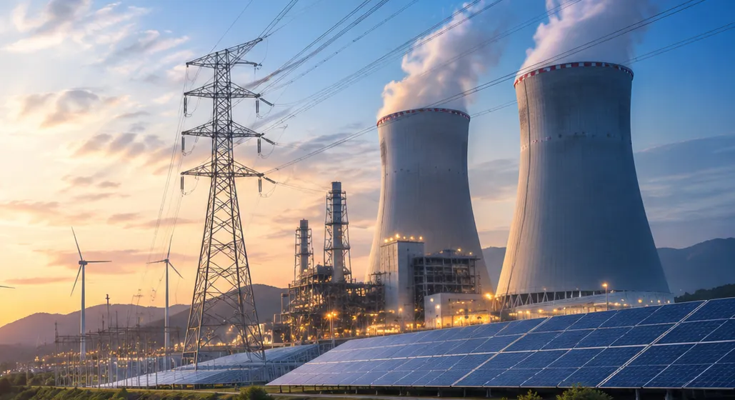
Industrial substations
- 220 kV
- 132 kV
- 110 kV
- 66 kV
- 33 kV
- 22 kV
- 11 kV
- Indoor GIS
- Outdoor AIS
- Compact
Industrial electrical distribution
15- Main receiving substations
- Main distribution boards
- HT switchgear
- LT switchgear
- Motor control centres
- Bus ducts
- Cable trays
- Power cables
- Distribution transformers
- Capacitor banks
- Harmonic filters
- Emergency power
- UPS systems
- Diesel generator systems
- Power monitoring
Specialised industrial infrastructure
12- Arc furnace power systems
- Rolling mill electrical systems
- Cement plant electrical systems
- Mining electrical systems
- Refinery electrical systems
- Chemical plant electrical systems
- Data centre electrical infrastructure
- Railway traction substations
- Metro traction substations
- Port electrical infrastructure
- Airport electrical infrastructure
- Water treatment and pumping stations
Data centres and digital infrastructure
Even short interruptions affect computing, telecom, cloud and digital services.
Data centre power infrastructure
16- Utility grid connection
- Multiple independent feeds
- EHV / HV receiving substations
- Transformer systems
- MV switchgear
- LV switchgear
- UPS systems
- Battery energy storage
- Backup generators
- Busway systems
- Power distribution units
- Static transfer switches
- Automatic transfer switches
- Power monitoring
- Protection and coordination
- Energy management
Data centre microgrids
10- Solar integration
- Wind integration
- Battery storage
- Fuel cells
- Backup generators
- Microgrid controller
- Redundant grid connections
- Critical load management
- Power quality management
- Energy optimisation
Railway, metro, port and airport
Railway electrification
12- Traction substations
- Switching posts
- Sectioning posts
- Sub-sectioning posts
- Traction transformers
- Traction switchgear
- OHE power supply
- SCADA
- Protection and control
- Return current systems
- Earthing and bonding
- Traction power monitoring
Metro rail
10- Traction power substations
- Auxiliary substations
- Receiving substations
- DC traction systems
- AC traction systems
- Rectifier transformers
- DC switchgear
- Regenerative braking energy
- Depot power systems
- Station distribution
Port and marine
10- Port substations
- Shore-to-ship power
- Crane power distribution
- Container terminal electrification
- Harbour networks
- Marine charging
- Port microgrids
- Renewable port infrastructure
- Battery storage
- Hydrogen integration
Airport
8- Receiving substations
- Runway lighting power
- Terminal distribution
- Ground support equipment charging
- Backup power
- Emergency distribution
- Data and communication
- Airport microgrids
Section 11
Grid equipment, products and materials
A procurement and supplier network for electrical equipment, grid components and infrastructure materials — ten product families, and the raw materials behind them.
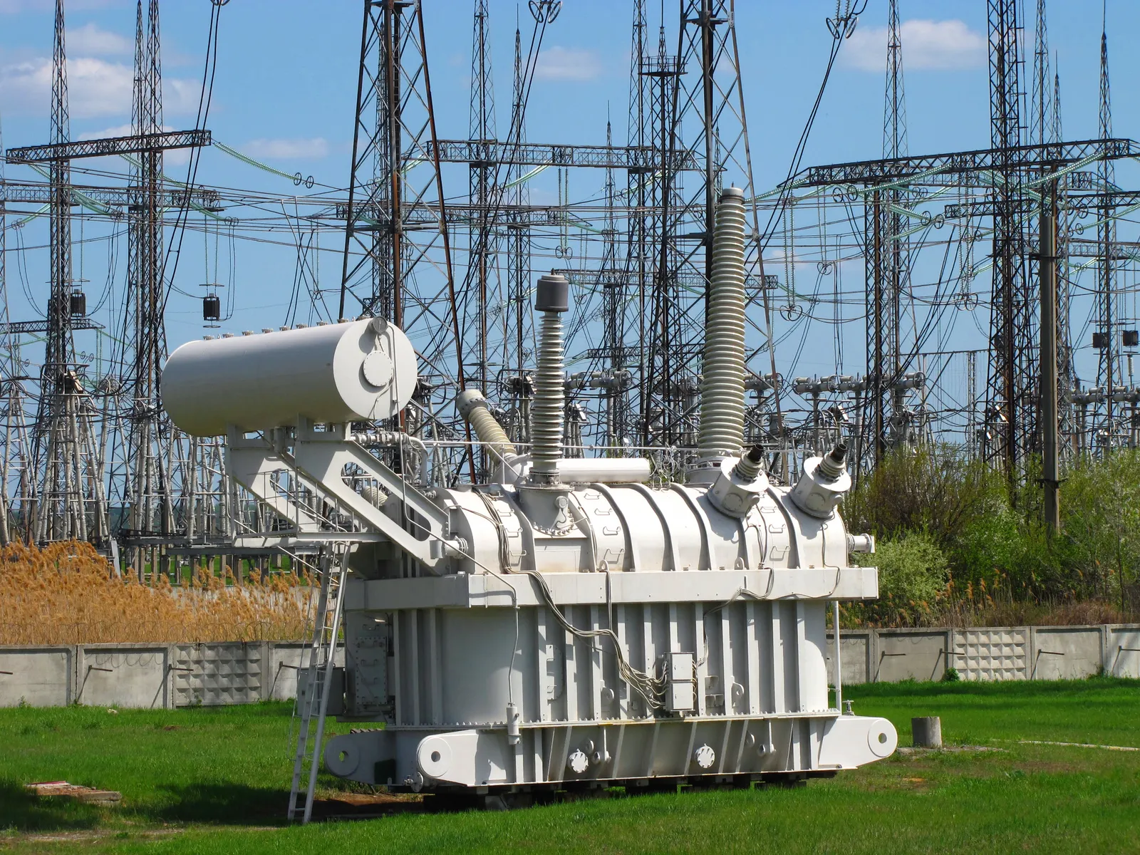
Product families
Power transformers
12- Generator transformers
- Power transformers
- Auto transformers
- Interconnecting transformers
- Distribution transformers
- Earthing transformers
- Furnace transformers
- Rectifier transformers
- Traction transformers
- Converter transformers
- Instrument transformers
- Special-purpose transformers
Switchgear and switching
14- SF₆ circuit breakers
- Vacuum circuit breakers
- Air circuit breakers
- Gas-insulated switchgear
- MV switchgear
- HV switchgear
- Disconnectors
- Earth switches
- Load break switches
- Ring Main Units
- Reclosers
- Sectionalisers
- Fuses
- Motorised switching
Insulating and interrupting technology must meet the applicable environmental requirements and equipment standards.
Instrument transformers and protection
11- Current transformers
- Voltage transformers
- Capacitive VTs
- Combined instrument transformers
- Optical instrument transformers
- Protection relays
- Metering relays
- Numerical relays
- Protection panels
- Control panels
- Relay test equipment
Busbar and insulation
12- Aluminium busbars
- Copper busbars
- Flexible connectors
- Bus ducts
- Bus supports
- Post insulators
- Disc insulators
- Long-rod insulators
- Composite insulators
- Bushings
- Cable terminations
- Insulation monitoring
Transmission line materials
14- Towers and tower members
- Bolts and nuts
- Conductors
- Earth wires
- OPGW
- Insulators
- Hardware fittings
- Clamps
- Spacers
- Dampers
- Foundations
- Earthing materials
- Aviation markers
- Line accessories
Underground cable materials
13- HT cables
- EHV cables
- XLPE cables
- MV cables
- LT cables
- Cable joints
- Terminations
- Link boxes
- Cable glands
- Cable trays
- Cable ducts
- Cable protection
- Cable test equipment
Reactive power and stability
10- Shunt reactors
- Series reactors
- Capacitor banks
- Series capacitors
- SVC
- STATCOM
- Synchronous condensers
- Harmonic filters
- PF correction panels
- Voltage regulators
Protection, automation and communication
13- Numerical relays
- RTUs
- SCADA systems
- Substation Automation Systems
- PLC systems
- DCS systems
- Communication gateways
- OPGW equipment
- Fibre optic cables
- Teleprotection
- Network switches
- Cybersecurity equipment
- GPS / time sync
Civil and mechanical
12- Structural steel
- Cement and concrete
- Reinforcement steel
- Foundation materials
- Cable trench materials
- Fire protection
- Oil containment
- Drainage
- Earthing electrodes
- Fencing and gates
- Equipment support structures
- Cable trays and supports
Microgrid and distributed energy
14- Solar PV modules
- Solar inverters
- Wind turbines
- Battery systems
- Battery inverters
- Bidirectional converters
- Energy management systems
- Microgrid controllers
- Diesel and gas generators
- Fuel cells
- Smart meters
- Energy monitoring
- Distribution transformers
- Protection equipment
Materials behind the equipment
Conductors
4- Electrical-grade aluminium and alloys
- Copper
- Steel and zinc
- Carbon fibre and composite cores
Structures
4- Carbon, high-tensile and galvanised steel
- Weathering and stainless steel
- Rebar, cement, aggregates
- Corrosion coatings
Insulation
6- Porcelain and toughened glass
- Silicone rubber and EPDM
- XLPE and EPR
- Epoxy and fibreglass
- Pressboard and insulation paper
- Mineral and ester oils
Gases & chemicals
6- SF₆ and alternative gas mixtures
- Nitrogen
- Transformer and ester fluids
- Silica gel and desiccants
- Jointing compounds
- Fire suppression agents
BARREL engineering principle
Long-lead items — EHV transformers, reactors, GIS and HVDC converters — are ordered from the critical path, type-tested designs are preferred, and every unit is inspected at the factory before dispatch. BARREL manufactures through OEM partners — T&D equipment.
Section 12
Testing, commissioning, inspection and O&M
Testing proves the infrastructure is installed correctly and performs to the approved design, the standards and the contract — and keeps proving it through its working life.
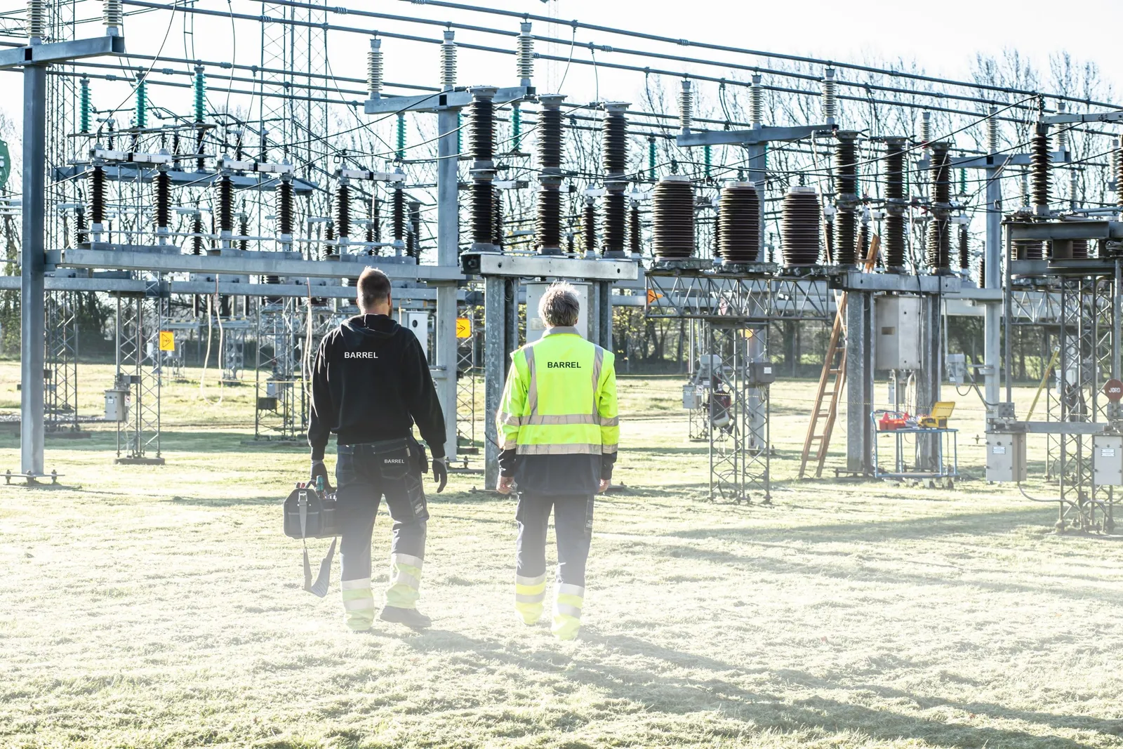
Where each test happens
- 1Type test (factory, once per design)
- 2Routine test (every unit, factory)
- 3FAT and inspection
- 4Site pre-commissioning
- 5Commissioning and energisation
- 6Trial operation
- 7Periodic O&M tests
Tests by asset
Transformer testing
14- Insulation resistance
- Winding resistance
- Turns ratio
- Vector group
- Magnetic balance
- Capacitance and tan delta
- Short-circuit impedance
- SFRA
- Oil BDV
- Dissolved Gas Analysis
- Bushing tests
- Protection testing
- Temperature indicators
- Functional tests
Circuit breaker testing
10- Contact resistance
- Insulation resistance
- Timing
- Travel measurement
- Opening and closing
- Trip and close coils
- Gas monitoring, where applicable
- Mechanism inspection
- Interlocks
- Functional operation
Transmission line testing
11- Conductor inspection
- Tower inspection
- Tower earthing resistance
- Insulator inspection
- Hardware inspection
- Sag and tension
- OPGW testing
- Fibre attenuation
- Continuity
- Line clearance
- Protection and teleprotection
Substation testing
15- CT testing
- PT / CVT testing
- Relay testing
- Primary injection
- Secondary injection
- Breaker testing
- Busbar protection
- Transformer protection
- Earthing system
- Interlocking
- AC / DC systems
- Battery capacity
- SCADA point-to-point
- Communication
- End-to-end protection
Microgrid testing
14- Grid synchronisation
- Islanding detection
- Transition to island
- Resynchronisation
- Black start
- Load shedding
- Battery control
- Generator dispatch
- Frequency control
- Voltage control
- Power quality
- Controller performance
- Emergency operation
- Protection coordination
Commissioning sequence
- 1Pre-commissioning inspection
- 2Mechanical and electrical completion
- 3Interlocking and protection verification
- 4SCADA, communication and metering checks
- 5Transformer and busbar energisation
- 6Line charging
- 7Grid synchronisation and load transfer
- 8Reliability run and handover
Energisation is earned, not declared
Inspection, maintenance and modernisation
Inspection and maintenance
16- Preventive
- Predictive
- Condition-based
- Thermography
- Partial discharge
- Transformer oil analysis
- SFRA
- Breaker maintenance
- Relay testing
- Cable testing
- Tower inspection
- Drone inspection
- OPGW inspection
- Earthing inspection
- Safety audit
- Asset health assessment
O&M also covers patrols, vegetation and right-of-way, GIS maintenance and condition monitoring — and modernisation: AIS-to-GIS, digital substations, reconductoring and dynamic line rating.
Section 13
Engineering studies, project development, EPC and digital tools
One coordinated delivery ecosystem — project owners, utilities, developers, engineers, manufacturers, contractors, investors and specialists — with the calculators and software that tie it together.

Electrical system studies
- Load flow
- Short-circuit
- Transient stability
- Voltage stability
- Small-signal stability
- Electromagnetic transients
- Harmonic analysis
- Insulation coordination
- Switching surge
- Lightning surge
- Protection coordination
- Arc flash
- Earthing
- Power quality
- Reactive power
- Contingency analysis
- N-1 reliability
- Grid impact assessment
- Renewable grid integration
Transmission line screening estimator
Change any value; presets fill typical conductor data. The first preset reproduces the worked example below.
Indicative line screening
- Resistive losses at this transfer
- 29.7 MW
- 2.97 % of the power sent · ≈ 112 GWh a year
- Current per circuit
- 760 A
- SIL per circuit
- 500 MW
- St Clair loadability
- 781 MW
- 1.56 × SIL at 250 km
- Thermal limit per circuit
- 1,145 MW
- Planning limit per circuit · utilisation
- 781 MW · 64 %
- governed by St Clair (voltage / stability); all circuits ≈ 1,563 MW
I = P ÷ (√3 V pf); loss = 3 I² R L; SIL = V² ÷ Zc; St Clair curve for loadability; LLF = 0.3 LF + 0.7 LF². A screening estimate for comparing options — not a load-flow, stability or design study.
Worked example — 400 kV double circuit, twin ACSR Moose, 250 km, 1,000 MW
Current per circuit
I = 500 MW ÷ (√3 × 400 kV × 0.95) ≈ 760 A
Losses, both circuits
2 × 3 × 760² × 0.0343 Ω/km × 250 km ≈ 29.7 MW
Surge impedance loading
SIL = 400² ÷ 320 Ω = 500 MW per circuit
St Clair loadability at 250 km
≈ 1.56 × 500 ≈ 781 MW per circuit
≈ 2.97 %
Resistive losses at 1,000 MW
≈ 1,563 MW
Planning limit, both circuits
≈ 64 %
Utilisation
≈ 112 GWh
Losses a year at 60 % load factor
Project development services
- Project identification
- Preliminary assessment
- Grid connectivity feasibility
- Power evacuation assessment
- Load flow and system studies
- Land identification
- Route alignment studies
- Right-of-way assessment
- Site survey and investigation
- Preliminary engineering
- Technical feasibility report
- Detailed Project Report
- Cost estimation
- Financing assessment
- Statutory and regulatory coordination
- Tender documentation
- Implementation planning
Engineering services
Electrical engineering
12- Single-line diagrams
- Substation layouts
- Switchyard layouts
- Equipment specifications
- Transformer specifications
- Busbar engineering
- Cable sizing
- Protection coordination
- Earthing design
- Lighting design
- Auxiliary power design
- System studies
Transmission engineering
10- Route alignment
- Tower spotting
- Tower design
- Foundation design
- Conductor selection
- Sag and tension
- Insulation coordination
- OPGW design
- Crossing design
- Line profile and survey
Civil and structural
11- Site development
- Soil investigation
- Substation foundations
- Transformer foundations
- Tower foundations
- Control room buildings
- Cable trenches
- Drainage
- Roads
- Structural steel
- Equipment supports
Mechanical
9- Transformer installation
- Busbar supports
- Equipment handling
- Oil handling
- Fire protection
- HVAC
- Cooling systems
- Cable supports
- Mechanical auxiliaries
Automation and communication
9- Protection architecture
- SCADA architecture
- SAS design
- PLC and RTU engineering
- Communication systems
- Teleprotection
- Network design
- Cybersecurity
- Remote monitoring
Complete EPC project execution — 24 steps
Coordinated as EPC or EPCM with qualified and authorised engineering and execution partners.
Develop
- 1Project identification
- 2Feasibility study
- 3Site and route assessment
- 4Grid connectivity planning
- 5Approvals and statutory coordination
Engineer
- 6Basic engineering
- 7FEED
- 8Detailed engineering
Procure & build
- 9Procurement and vendor finalisation
- 10Civil construction
- 11Structural construction
- 12Manufacturing and supply
- 13Mechanical installation
- 14Electrical installation
- 15Instrumentation and automation
- 16Communication and cybersecurity
Test & energise
- 17Testing and inspection
- 18Pre-commissioning
- 19Commissioning
- 20Grid synchronisation and energisation
- 21Performance verification
Operate
- 22Project handover
- 23O&M and lifecycle support
- 24Modernisation, uprating and decommissioning
A separate BOQ for every package
- 1. Line supply
- 2. Line erection
- 3. Tower foundations and civil
- 4. Stringing and accessories
- 5. Underground cable supply
- 6. Cable laying and jointing
- 7. Substation primary equipment
- 8. Substation secondary equipment
- 9. Control, protection and automation
- 10. Civil and structural
- 11. Fire protection and auxiliaries
- 12. Testing and commissioning
- 13. Operation and maintenance
Project delivery models
- 01
EPC
Engineering, Procurement and Construction — single-point delivery of the agreed scope.
- 02
EPCM
Engineering, Procurement and Construction Management for the owner.
- 03
Turnkey
Complete facility handed over ready to operate.
- 04
Design and Build
One party designs and constructs.
- 05
Supply and installation
Equipment supply with erection and installation by BARREL or its partners.
- 06
BOO / BOOT / BOT
Build, Own, Operate (and Transfer), or Build, Operate, Transfer, under a long-term arrangement.
- 07
PPP
Public-Private Partnership.
- 08
TBCB
Tariff-Based Competitive Bidding for transmission projects.
- 09
JV / Consortium
Joint venture or consortium with qualified partners.
- 10
Framework and rate contracts
Multi-year call-off contracts at agreed rates for utilities and large owners.
- 11
PMC
Project Management Consultancy.
- 12
Owner's / Independent Engineer
Design review, supervision and lender's assurance.
- 13
Asset management
Long-term asset management contracts.
- 14
O&M contracts
Operation and maintenance of lines, substations and microgrids.
What BARREL commits to is defined per project
BARREL Grid Infrastructure Intelligence Centre
Planned as a working platform of six connected systems for power-sector professionals. The line estimator above is its first public tool.
- 01
Grid Engineering Centre
Calculations, system studies, designs and technical specifications.
- 02
Substation & Transmission Project Centre
Project development, BOQ, costing, tenders and EPC management.
- 03
Microgrid Design Centre
Load analysis, generation and battery sizing, islanding and economic optimisation.
- 04
Equipment & Procurement Centre
Catalogues, technical comparison, OEMs, suppliers and purchase enquiries.
- 05
Grid Asset Management Centre
Inspections, testing, maintenance, equipment health and lifecycle management.
- 06
Grid Finance & Investment Centre
Feasibility, CAPEX, OPEX, financing, investment and commercial modelling.
Substation tools
13- Transformer sizing
- Transformer impedance
- Short-circuit calculation
- Circuit breaker rating
- Busbar sizing
- CT / PT selection
- Cable sizing
- Earthing grid
- Battery sizing
- Capacitor bank sizing
- Reactor sizing
- Auxiliary power sizing
- Substation BOQ
Transmission tools
11- Line capacity
- Conductor selection
- Voltage drop
- Line losses
- Sag and tension
- Tower loading
- Foundation quantities
- OPGW selection
- Route length
- Corona assessment
- Project cost
Distribution tools
8- Feeder load
- DT sizing
- Voltage drop
- Cable sizing
- Network losses
- Network cost
- Load forecasting
- Feeder segregation planning
Microgrid tools
11- Peak demand
- Daily energy
- Solar and wind sizing
- Battery energy and power
- Generator sizing
- Critical load
- Autonomy
- Islanding capability
- Renewable penetration
- Microgrid LCOE
- Payback and IRR
Project costing and BOQ
16- Substation CAPEX
- Line cost
- Pooling substation
- Evacuation cost
- Distribution network cost
- Microgrid cost
- Equipment BOQ
- Material quantities
- Civil works
- Foundations
- Cables
- Labour and installation
- Testing and commissioning
- O&M cost
- Contingency
- Lifecycle cost
Project development software
16- Grid connectivity management
- Transmission route planning
- GIS network mapping
- Substation site assessment
- Land and right-of-way tracking
- Project feasibility
- Technical bid preparation
- Specification generation
- Tender management
- BOQ preparation
- Cost estimation
- Finance modelling
- Schedule management
- Contractor management
- Quality inspection
- Commissioning documentation
Grid asset intelligence
14- Transformer register
- Substation register
- Line register
- Distribution register
- Lifecycle tracking
- Maintenance schedules
- Inspection records
- Fault history
- Failure analysis
- Condition monitoring
- Predictive maintenance
- Asset health index
- Spare parts
- Replacement planning
Grid digital twin
12- Digital substation model
- Transmission line model
- Distribution network model
- Transformer health model
- Network topology
- Live equipment status
- Power flow visualisation
- Fault visualisation
- Renewable integration
- Battery monitoring
- Microgrid simulation
- Asset performance analytics
BARREL grid marketplace connects
13- Project owners
- Utilities
- Renewable developers
- Substation EPC companies
- Transmission contractors
- Equipment manufacturers
- Electrical suppliers
- Testing agencies
- O&M providers
- Microgrid developers
- Investors
- Engineering consultants
- International trading partners
BARREL OS
BARREL OS and BARREL AI bring project records, drawings, procurement, site progress and O&M data for substations, lines and microgrids into one place.
See also BARREL's nine-thread project lifecycle used across all power projects.
Section 14
Business opportunities, divisions and partner network
Grid infrastructure creates business across asset development, construction, equipment, maintenance, operations, financing and technology — in India and abroad. Twelve BARREL divisions and a partner network deliver it.

Business opportunities
Transmission business
12- Project development
- Line construction
- Transmission EPC
- Tower manufacturing
- Conductor supply
- OPGW supply and installation
- Underground cable projects
- Submarine cable projects
- HVDC projects
- Asset acquisition
- Network modernisation
- Transmission O&M
Substation business
13- Greenfield substations
- Brownfield expansion
- AIS EPC
- GIS EPC
- Hybrid substations
- Transformer supply
- Switchgear supply
- Protection and control
- Substation automation
- Refurbishment
- Bay extensions
- Mobile substations
- Substation O&M
Renewable grid infrastructure
11- Solar evacuation
- Wind evacuation
- Hybrid pooling substations
- Renewable energy parks
- Dedicated lines
- Grid connectivity
- Renewable forecasting
- Grid integration
- BESS grid connection
- Pumped storage connection
- Curtailment management
Distribution business
10- Distribution substations
- Line construction
- Underground cabling
- Feeder segregation
- Transformer installation
- Smart meters
- Distribution automation
- Network rehabilitation
- Loss reduction
- Utility modernisation
Microgrid business
11- Industrial
- Commercial
- Community
- Rural electrification
- Remote-area
- Renewable
- Battery-integrated
- Hydrogen-based
- Data centre
- Energy-as-a-Service
- Microgrid O&M
Investment and finance
13- Transmission investment
- Substation assets
- Distribution infrastructure
- Renewable evacuation
- Microgrid projects
- Infrastructure SPVs
- Project finance
- Equipment financing
- Leasing
- Infrastructure funds
- Asset monetisation
- Joint ventures
- Concessions
International grid infrastructure market
Electrification, renewables, data centres, e-mobility and storage are driving new transmission and distribution worldwide.
Opportunities
14- National transmission networks
- Regional interconnections
- Cross-border transmission
- Renewable evacuation
- Offshore wind grid connections
- HVDC
- Grid-scale storage
- Smart grid modernisation
- Digital substations
- Distribution rehabilitation
- Industrial power
- Remote-community microgrids
- Resilient power systems
- Automation and cybersecurity
Markets
10- India
- Middle East
- Africa
- Southeast Asia
- Europe
- United Kingdom
- United States
- Australia
- Latin America
- Central Asia
Business models
12- International EPC
- Equipment export
- OEM representation
- Technology licensing
- Joint ventures
- Local manufacturing partnerships
- Engineering consultancy
- Infrastructure investment
- Transmission concessions
- Project development
- Cross-border equipment trading
- Long-term O&M
BARREL grid infrastructure divisions
- Division 01
BARREL Grid Development
Project identification, feasibility, grid planning, connectivity, land, route alignment and infrastructure development.
- Division 02
BARREL Substation Engineering & EPC
Grid and pooling substations, switchyards, AIS, GIS, hybrid substations, bay extensions and turnkey execution.
- Division 03
BARREL Transmission Infrastructure
Overhead lines, towers, conductors, OPGW, underground and submarine cables and HVDC systems.
- Division 04
BARREL Distribution Infrastructure
Distribution substations, feeders, transformers, underground networks, rural electrification and utility modernisation.
- Division 05
BARREL Microgrid & Distributed Energy
Industrial, commercial, institutional, community, rural, remote-area and renewable microgrids.
- Division 06
BARREL Smart Grid & Automation
SCADA, EMS, DMS, digital substations, protection, communication, cybersecurity and intelligent grid management.
- Division 07
BARREL Grid Stability & Power Quality
FACTS, STATCOM, SVC, reactive compensation, harmonic filters, synchronous condensers and stability solutions.
- Division 08
BARREL Grid Equipment & Manufacturing
Transformers, switchgear, conductors, towers, cables, insulators, protection systems and OEM partnerships.
- Division 09
BARREL Testing, Inspection & O&M
Testing, commissioning, relay and transformer testing, inspection, maintenance, condition monitoring and asset management.
- Division 10
BARREL Grid Finance & Investment
Infrastructure finance, project SPVs, asset investment, transmission projects, leasing, joint ventures and funding.
- Division 11
BARREL Grid Trade & Supply Chain
Equipment procurement, manufacturing partnerships, domestic distribution, international trading, imports and exports.
- Division 12
BARREL Grid Intelligence Centre
Engineering calculators, network studies, BOQ, project costing, digital twins, AI, GIS and asset intelligence.
Authorised grid infrastructure partner network
Authorised Grid Equipment Supplier Partner
19- Power and auto transformers
- Circuit breakers
- GIS and AIS switchgear
- VCB panels
- Isolators
- CTs and PTs
- Protection relays
- Control panels
- Conductors
- Towers
- Insulators
- OPGW
- Power cables
- Earthing materials
- Capacitor banks
- Reactors
- SCADA equipment
- Battery systems
- Microgrid controllers
Authorised Grid Contractor
12- Substation construction
- Line construction
- Tower erection
- Conductor stringing
- Cable laying
- Cable jointing
- Transformer installation
- Switchyard construction
- Civil and structural works
- Electrical installation
- Protection and control installation
- Testing and commissioning
Authorised Grid Service Provider
15- Transformer testing and repair
- Breaker maintenance
- Relay testing
- Cable testing
- Thermography
- Partial discharge testing
- Earthing testing
- Tower inspection
- Drone surveys
- OPGW testing
- SCADA maintenance
- Substation O&M
- Line O&M
- Microgrid O&M
- Energy audits
Grid Technology Partner
10- Smart grid technology
- Digital substations
- Protection and automation
- Grid software
- Microgrid technology
- Battery storage technology
- Power electronics
- Power quality technology
- Cybersecurity
- Research institutions
Grid Project Partner
10- Project developers
- Landowners
- Infrastructure companies
- Utilities
- Renewable developers
- Industrial consumers
- EPC companies
- Investors
- Financial institutions
- International developers
Registration is not a technical endorsement
Section 15
Indian regulatory framework and international standards
Grid infrastructure in India is governed by electricity law, technical standards, connectivity requirements, planning criteria, safety regulations and grid codes — central and state.

Key Indian institutions
| Institution | Relevant role |
|---|---|
| Ministry of Power | Electricity policy and sector administration |
| Central Electricity Authority (CEA) | Technical standards, planning and advisory functions |
| Central Electricity Regulatory Commission (CERC) | Regulation of inter-state electricity and transmission |
| State Electricity Regulatory Commissions (SERCs) | State-level electricity regulation |
| Central Transmission Utility of India Ltd (CTUIL) | Inter-state transmission planning and connectivity |
| Power Grid Corporation of India Ltd | Major transmission developer and operator |
| Grid Controller of India — NLDC | National grid operation |
| Regional Load Despatch Centres | Regional grid operation |
| State Load Despatch Centres | State grid operation |
| State Transmission Utilities | State transmission planning and coordination |
| Distribution licensees | Electricity distribution and consumer supply |
Important Indian regulations and technical frameworks
Check the latest amendments, applicable jurisdiction and project requirements before design or execution.
| Regulation / document | Relevance |
|---|---|
| Electricity Act, 2003 | Principal electricity-sector legislation |
| CEA Technical Standards for Construction of Electrical Plants and Electric Lines Regulations, 2022 (as amended) | Technical construction requirements |
| CEA Safety Requirements for Construction, Operation and Maintenance Regulations, 2011 (as amended) | Safety during construction, operation and maintenance |
| CEA Measures relating to Safety and Electric Supply Regulations, 2023 | Electrical safety requirements |
| CEA Manual on Transmission Planning Criteria | Transmission network planning |
| CERC Indian Electricity Grid Code Regulations, 2023 | Grid operation, connectivity and system requirements |
| CERC Connectivity and General Network Access Regulations, 2022 (as amended) | Inter-state transmission connectivity |
| CEA Technical Standards for Connectivity to the Grid | Grid connectivity requirements |
| CEA Technical Standards for Communication System in Power System Operations Regulations, 2020 | Power system communication |
| CEA Metering Regulations (as applicable) | Electricity metering |
| State Grid Codes and Distribution Codes | State-level network requirements |
CEA publishes the Transmission Planning Criteria manual and construction standards with amendments on cea.nic.in; the Grid Code 2023 and GNA regulations are on cercind.gov.in.
International technical standards
- IEC 60038DesignStandard voltages
- IEC 60076EquipmentPower transformers
- IEC 62271 seriesEquipmentHigh-voltage switchgear and controlgear
- IEC 61850AutomationSubstation automation and communication
- IEC 60255ProtectionMeasuring relays and protection equipment
- IEC 60071DesignInsulation coordination
- IEC 61936-1DesignPower installations exceeding 1 kV AC
- IEC 60502CablesPower cables
- IEC 60840CablesEHV cable systems
- IEC 62067CablesHigher-voltage extruded cable systems
- IEC 60099EquipmentSurge arresters
- IEC 60826LinesOverhead line design criteria
- IEC 61284 / 60383LinesOverhead line fittings / line insulators
- IEC 60270EquipmentPartial discharge measurement
- IEC 60909DesignShort-circuit currents
- IEC 62305DesignLightning protection
- IEEE C37 seriesEquipmentSwitchgear and circuit breakers
- IEC 61400DesignWind energy systems
- IEC 62443AutomationIndustrial automation cybersecurity
- IEEE 80DesignSubstation grounding
- IEEE 81DesignEarth resistivity and grounding measurements
- IEEE 738LinesCurrent-temperature of bare overhead conductors
- IEEE 519ProtectionHarmonic control in power systems
- IEEE 1547MicrogridInterconnection of distributed energy resources
- IEEE 2030.9MicrogridMicrogrid planning and design
- IEEE 2030.7MicrogridMicrogrid controller functional specification
- NFPA 70SafetyNational Electrical Code, where applicable
- NFPA 70ESafetyElectrical safety in the workplace, where applicable
Bodies: IEC · IEEE · CIGRE · CEA India · BIS · ANSI · ASTM · ASME · ISO · EN / CENELEC · NFPA · NEMA · UL · CSA · AS/NZS. Exact editions, amendments and national adoption are recorded per project.
Standards are not interchangeable — and listing one is not compliance
Section 16
Why BARREL, FAQs and references
From generation connectivity to the consumer's network — one connected infrastructure ecosystem.
Why choose BARREL for grid infrastructure?
- Generation-to-grid connectivity
- Pooling substation development
- Grid substation engineering
- Transmission line infrastructure
- HVDC and advanced transmission
- Distribution infrastructure
- Industrial power systems
- Microgrid development
- Renewable integration
- Battery storage integration
- Smart grid and automation
- Protection and control
- Equipment and OEM partnerships
- Project procurement
- EPC and construction coordination
- Testing and commissioning
- Operation and maintenance
- Infrastructure investment
- Domestic and international trading
- Digital grid intelligence
Frequently asked questions
Q1What is grid infrastructure?
The electrical networks and equipment that connect generation, transmit electricity, transform voltage, distribute power and supply consumers.
Q2What is a grid substation?
An electrical facility for switching, transforming, protecting, controlling and routing electricity within the power network.
Q3What is a pooling substation?
A substation that collects electricity from several generating units or renewable projects and transfers the combined power to the transmission network.
Q4What is the difference between a grid substation and a pooling substation?
A grid substation mainly transforms, switches and interconnects the network. A pooling substation specifically consolidates power from several generating sources before evacuation. One facility can do both.
Q5What is an AIS substation?
An Air Insulated Substation uses air as the principal insulation between outdoor electrical equipment.
Q6What is a GIS substation?
A Gas Insulated Substation uses compact metal-enclosed switchgear with an insulating gas or alternative insulation medium.
Q7What is a transmission line?
A line that carries bulk electrical power between generating stations, substations and major network points.
Q8What is the difference between transmission and distribution?
Transmission carries bulk electricity over longer distances, usually at higher voltages. Distribution delivers electricity from substations to end consumers.
Q9What is HVDC transmission?
High Voltage Direct Current transmission transfers power using DC. It suits certain long-distance, submarine, underground and asynchronous interconnection applications.
Q10What is a microgrid?
A local electrical network that coordinates generation, storage and loads, and can run connected to the main grid or on its own if designed for islanded operation.
Q11Can a microgrid operate without the main grid?
Yes, if it is designed for it: islanded operation needs suitable local generation and storage and the right control, protection and reserve arrangements.
Q12What is a hybrid microgrid?
A microgrid that combines two or more power sources — often renewables, battery storage and backup generation.
Q13What is a smart grid?
A grid that uses digital communication, automation, sensors and intelligent control to improve how the network is operated.
Q14What is a digital substation?
A substation that uses digital communication, intelligent electronic devices and automated protection and control — typically on IEC 61850.
Q15What is SCADA?
Supervisory Control and Data Acquisition — a system to remotely monitor and control electrical infrastructure and industrial processes.
Q16What is a STATCOM?
A power-electronic device that provides dynamic reactive power and helps control voltage in the network.
Q17What is a pooling station for solar power?
It collects electricity from several solar units or projects through collection feeders and connects the combined output to the transmission network.
Q18What is renewable energy evacuation?
The electrical infrastructure that carries renewable electricity from the generating site to the grid connection point.
Q19What is OPGW?
Optical Ground Wire — the shield wire of a transmission line with optical fibres inside, used for communication and protection signalling.
Q20What is a grid-connected battery storage system?
A battery facility connected to the network to provide services such as energy shifting, frequency response and grid support.
Q21What is a generation switchyard?
The facility that connects a generating station to the transmission network through transformers, busbars, breakers and protection.
Q22What is a bay extension?
Adding a new circuit or equipment connection to an existing substation, subject to design compatibility and system requirements.
Q23What is grid stability?
The ability of a power system to keep or regain acceptable operating conditions after a disturbance.
Q24What is power evacuation infrastructure?
The complete electrical system that transfers electricity from a power plant to its designated grid interconnection point.
Q25Can BARREL support turnkey substation and transmission projects?
BARREL coordinates development, engineering, procurement, construction, testing and commissioning through its own capabilities and qualified partners, within the scope and contract of each project.
Q26Can BARREL support industrial microgrid projects?
Yes — feasibility, load assessment, renewable and storage integration, electrical design, control systems, EPC coordination and O&M.
Q27Does BARREL support transmission line construction?
The transmission offering covers route surveys, tower and foundation engineering, procurement, erection, stringing, OPGW, testing and commissioning.
Q28Can BARREL help with grid connectivity for solar and wind projects?
Yes — evacuation planning, pooling substations, transmission lines, connectivity coordination and the associated electrical infrastructure.
Q29Does BARREL support substation testing and commissioning?
Transformer, breaker, relay, SCADA and protection testing, pre-commissioning and commissioning — through appropriately qualified specialists.
Q30What is the future of grid infrastructure?
Conventional transmission combined with renewables, storage, HVDC, digital substations, smart distribution, microgrids, advanced power electronics and intelligent energy management.
Technical reference library
- CEA (India)Central Electricity Authority — regulations, transmission planning criteria, standards
- CERC (India)Central Electricity Regulatory Commission — Grid Code 2023, GNA regulations
- CTUIL (India)Central Transmission Utility of India — ISTS planning and connectivity
- Grid-IndiaGrid Controller of India — national and regional load despatch
- Ministry of PowerMinistry of Power, Government of India — transmission and distribution policy
- IECInternational Electrotechnical Commission — IEC 61850, 62271, 60076 and more
- IEEE SAIEEE Standards Association — IEEE 80, 1547, 2030.7, 2030.9
- CIGREInternational Council on Large Electric Systems — technical brochures
- IEAInternational Energy Agency — Electricity grids and secure energy transitions
- U.S. DOEOffice of Electricity — microgrids and grid modernisation
- IECIEC 60038 — standard voltages
- POWERGRID (India)Power Grid Corporation of India — technical specifications
- IEEE PESIEEE Power & Energy Society
Related BARREL pages
Powering the networks that power the world
Connect your power infrastructure opportunities with BARREL.
Developing a transmission project, building a substation, evacuating renewable energy, modernising a distribution network, setting up an industrial microgrid or sourcing electrical equipment — BARREL is building an ecosystem that connects the right technical, commercial and execution capabilities.
Connect with BARREL for
- Grid substations and switchyards
- Pooling substations and evacuation
- Transmission lines and cables
- HVDC and FACTS
- Distribution networks
- Microgrids
- Smart grid, SCADA and protection
- Grid equipment and OEMs
- Testing, commissioning and O&M
- Investment and project finance
BARREL.ENERGY · One World. One Power Network. Rooted in Bharat. Global by Vision.