
- Renewable Generation
- Floating Solar
- Water Bodies
- Turnkey EPC
Floating Solar
Reservoirs | Hydro Dams | Lakes | Ponds | Floats | Mooring
Solar power that saves land and water.
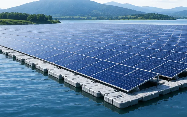
Floating solar places PV arrays on platforms anchored on reservoirs, hydro dams, lakes, industrial ponds and mine pits. It needs no farmland, the water keeps the panels cooler and the cover cuts evaporation. BARREL supports floating projects from bathymetry and environmental studies through float and mooring design, approvals, installation and grid connection to O&M on the water.
WWater body
Depth, level swing, wind and waves
FFloats
UV-stable HDPE platforms and walkways
MMooring
Anchors and lines that follow the water level
- Plant size
- 100 kW–600 MW
- Water area per MWp
- ~1.0–1.5 ha
- Cooling gain (indicative)
- 2–8 %
- Design life
- 25+ yrs
- Grid connection
- 11–220 kV
Section 01
Floating Solar — Overview
A floating PV plant mounts solar modules on buoyant platforms held in place by anchors and mooring lines. Power is collected through floating or underwater cables to inverters and a substation on shore.
India has large irrigation, hydro and water-supply reservoirs, many of them near existing grid infrastructure. Several large floating plants have already been built on reservoirs in central and southern India, and many more are planned.
1.1Where floating solar is used
| Water body | Typical size | Points to note |
|---|---|---|
| Hydro reservoirs | 10–600 MW | Large level swings; existing grid connection; hybrid operation |
| Irrigation and water-supply reservoirs | 5–100 MW | Drinking-water rules for materials; seasonal levels |
| Natural lakes | 1–50 MW | Ecology and tourism sensitivities; coverage limits |
| Industrial and power-plant ponds | 1–50 MW | Ash or cooling ponds near plant loads |
| Aquaculture and village ponds | 100 kW–5 MW | Shared use with fish farming |
| Mine pits and quarry lakes | 1–50 MW | Reuses degraded land; water chemistry |
1.2Why floating solar
01
Saves land
No farmland or forest needed; useful where land is costly or contested.
02
Cooler modules
Water below the array keeps modules cooler, raising output by a few per cent.
03
Saves water
Cover reduces evaporation from the reservoir, valuable in dry regions.
04
Uses existing grid
Hydro and pumping stations already have substations and lines.
05
Less algae
Shading can reduce algal growth in some water bodies.
06
Hybrid with hydro
Solar by day lets hydro save water for evening peaks.
Section 02
Float Systems and Platforms
Floats carry the modules, inverters and walkways and must survive 25 years of sun, waves and level changes. Most systems use UV-stabilised high-density polyethylene (HDPE).
01
Most commonPure-float HDPE
Blow-moulded floats linked by pins form a flexible mat; modules sit directly on main floats with walkway floats between rows.
02
TiltedPontoon with metal frame
HDPE or composite pontoons carry a galvanised or aluminium frame that holds modules at a chosen tilt.
03
EmergingMembrane and mat
Thin flexible membranes or mats with modules laid flat, for sheltered waters.
04
FloatingInverter and transformer platforms
Larger pontoons carry string or central inverters and transformers when shore space is far away.
05
SpecialisedTracking floats
Rotating platforms that follow the sun, used in a few projects.
06
Early stageNear-shore and offshore
Heavier systems for waves on bays and seas, still in demonstration.
2.1What to ask of a float
- HDPE grade with UV stabilisers and long-term weathering data
- Food-grade or potable-water approved materials where needed
- Buoyancy reserve under module, people and snow or debris loads
- Fatigue life of links and pins under wave motion
- Fire behaviour of the material
- Recyclability at end of life
Section 03
Site Data, Layout and Energy Yield
A floating plant is designed around the water body: how deep it is, how far the level moves, where the wind blows from and how big the waves get across the open fetch.
3.1Annual energy of a floating plant
Annual energy
E (kWh/yr) = P × PSH × PR × (1 + gcool) × 365
Example (indicative): 10,000 kWp × 5.0 × 0.78 × 1.03 × 365 ≈ 147 lakh kWh per year
Peak sun hours are the daily irradiation on the panel plane (kWh/m²). Floating arrays usually sit at low tilt, so plane irradiation can be slightly lower than for a ground plant at optimum tilt. The cooling gain depends on wind, float type and climate; measured gains vary and should be assumed conservatively.
| Symbol | Meaning |
|---|---|
| P | DC capacity, kWp |
| PSH | Peak sun hours on the panel plane, h/day |
| PR | Performance ratio before cooling effect, typically 0.75–0.82 |
| gcool | Cooling gain, about 0.02–0.08 (indicative, site-dependent) |
3.2Site investigations
Water and weather
5- Bathymetric survey of the bed (echo sounder, sonar)
- Reservoir level series: minimum, maximum and rate of change
- Wind speed and direction, extreme gusts
- Wave height from fetch and wind
- Currents, inflows, spillway and intake zones
Bed and shore
5- Soil and rock of the reservoir bed for anchors
- Sediment depth and siltation
- Shoreline access for assembly and launch
- Space for inverters, substation and stores
- Debris and floating vegetation in floods
Section 04
Anchoring, Mooring and Water-Level Variation
The mooring system keeps the array in place in storms and lets it rise and fall with the water. On hydro reservoirs the level can move by tens of metres between monsoon and summer.
4.1Anchor types
| Anchor | Where used | Notes |
|---|---|---|
| Bank anchoring | Small ponds, narrow water bodies | Lines tied to shore blocks; simple but limited by distance |
| Concrete deadweight blocks | Most reservoirs with soft beds | Sunk from barges; holding by weight and friction |
| Driven or helical piles | Firm soil beds, shallow water | High holding per anchor; needs piling equipment |
| Drag-embedment anchors | Deeper water with suitable soil | Set by pulling; proven marine technology |
| Rock anchors | Rocky reservoir beds | Drilled and grouted by divers or remote tools |
4.2Mooring design points
- Elastic or chain-and-rope lines that take up slack as levels change
- Line length and angle checked at minimum and maximum water level
- Array never grounds on the bed at low water, or is designed to rest safely
- Load analysis for wind, waves and current, including extreme events
- Redundancy so one failed line does not release the array
- Corrosion and abrasion protection for chains and shackles
- Separation from spillways, intakes and navigation channels
Guidance such as DNV-RP-0584 on floating solar design and operation is widely used by lenders; IEC work on floating PV standards is in progress.
Section 05
Electrical Design, Cable Routing and Grid Connection
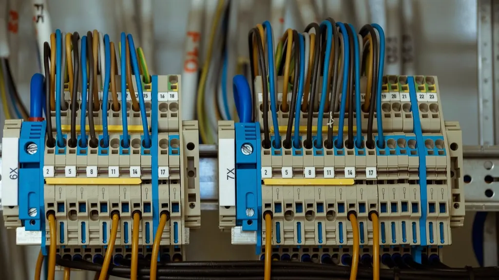
Water and electricity demand careful design: every cable must tolerate movement and wetting, and earthing must work across a floating, moving array.
On the array
5- String cables in trays clipped to floats
- UV- and water-resistant DC cables
- Connectors kept above water
- Equipotential bonding of frames
- String or central inverters on floats or shore
Array to shore
5- Floating cable routes with service loops
- Submarine-rated or water-tolerant cables on the bed
- Slack for full water-level range
- Strain relief at the shoreline
- Marked routes to avoid boat damage
Shore and grid
5- Inverter and transformer stations
- Pooling substation at 33–220 kV
- Shared bay at the hydro switchyard where allowed
- SCADA and forecasting to load despatch
- Lightning protection for the open water area
Section 06
Hybrid Operation with Hydropower
A floating plant on a hydro reservoir can share the dam's grid connection and let the hydro units hold back water during sunny hours for release in the evening peak.
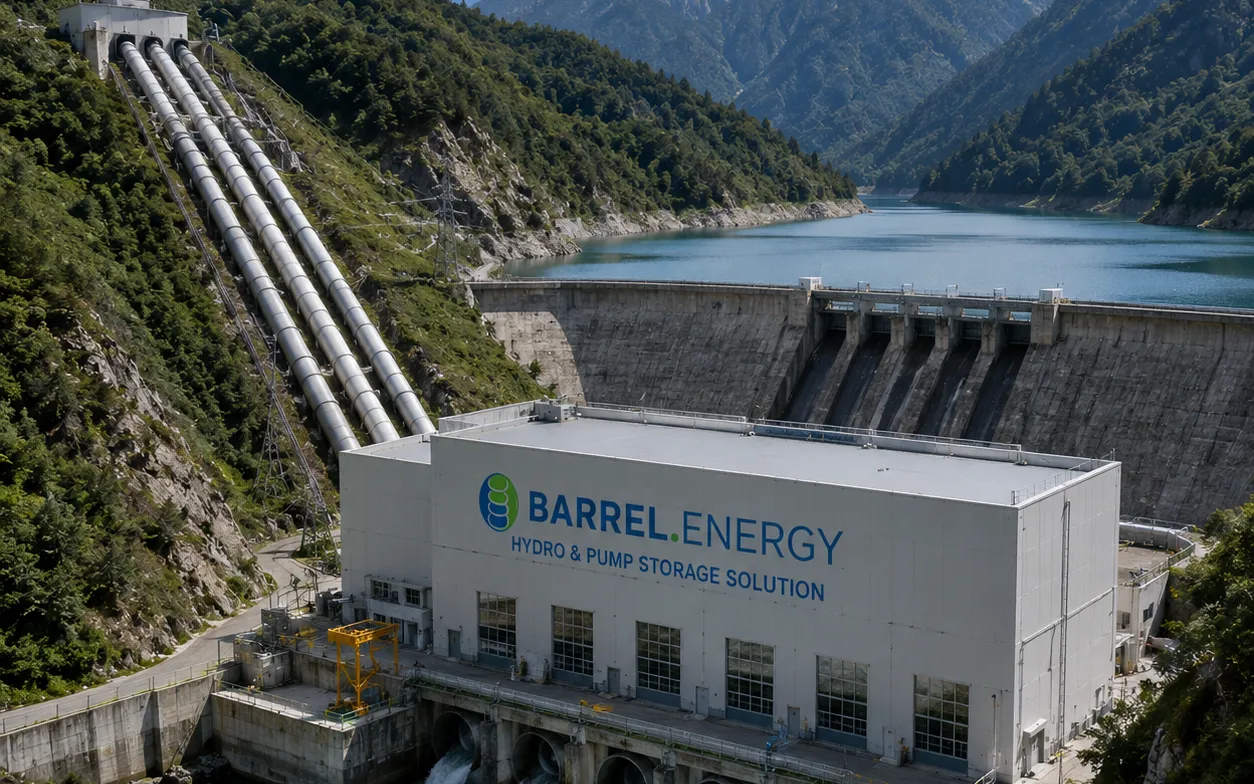
6.1A sunny day on a hybrid reservoir
- Morning: solar ramps up
- Midday: hydro throttled back
- Water saved in reservoir
- Evening: hydro meets the peak
- Night: hydro alone
6.2Benefits and checks
01
Shared evacuation
Existing lines and substations can carry solar output when hydro is low, subject to capacity and approval.
02
Firmer supply
Hydro balances solar variability within minutes, giving a smoother combined output.
03
Water value
Water saved by day and by lower evaporation becomes extra peak energy.
04
Operating rules
Dam safety, irrigation releases and flood rules come first; the solar layout must respect them.
Section 07
Environmental and Social Studies
Covering part of a water body changes light, temperature and oxygen below it. Studies before and during operation show whether the effects are acceptable and guide how much area may be covered.
- Baseline water quality: oxygen, temperature, nutrients, algae
- Fish, birds and aquatic plants survey
- Coverage limit as a share of the water surface
- Evaporation saving estimate
- Material leaching tests for drinking-water reservoirs
- Fisheries and livelihood consultations
- Navigation, tourism and religious uses
- Construction-phase spill and waste control
- Monitoring plan for the operating years
- Decommissioning and float recycling plan
Evaporation saving under the array can be large, but the overall saving depends on the share of the water body covered and the local climate; quote figures from site studies, not general rules.
Section 08
Project Development and Approvals
The owner of the water body — usually a state water resources department, a hydro utility or an industry — must agree to its use before anything else can move.
- 1Water-body screening and pre-feasibility
- 2Lease or use agreement with the water-body owner
- 3Bathymetry, level, wind and soil studies
- 4Environmental and social assessment
- 5Detailed project report and float and mooring design
- 6Consents from water resources, dam safety and fisheries authorities as applicable
- 7Grid connectivity and power purchase agreement
- 8Shore land for assembly yard and substation
- 9Financial close and EPC award
Section 09
Turnkey EPC and Installation
Floating arrays are assembled on shore in sections, pushed onto the water, towed into place and connected to the anchors. A good launch yard sets the pace of the whole project.
9.1Installation sequence
- Shore assembly yard
- Float and module assembly
- Launch ramp
- Tow by boat
- Anchor and moor
- Cable to shore
- Testing & commissioning
Marine works
4- Anchor fabrication and placement
- Barges, workboats and divers
- Mooring line installation and tensioning
- Cable laying on the bed
Array
4- Float and module assembly
- DC cabling and combiner boxes
- Walkways and safety rails
- Inverter platforms if floating
Shore and grid
4- Inverter stations and transformers
- Substation and transmission line
- SCADA and security
- Stores and O&M jetty
Section 10
Operation and Maintenance on Water
Most maintenance is done from walkways and boats. Birds, algae and moorings add tasks that a land plant does not have.
- Module cleaning with reservoir water, bird-dropping removal
- Inspection of float links, pins and walkways
- Mooring line tension and anchor checks, more often in storms
- Re-tensioning as water level changes
- Cable route and connector inspection
- Thermal imaging by drone
- Bird deterrents where needed
- Removal of floating debris and weeds
- Boat, life-jacket and rescue drills for staff
- Environmental monitoring as permitted
Staff must be trained for work on and near water; at least two people and a rescue boat should be present for any work on the array.
Section 11
Finance and Commercial Models
Floating solar usually costs more to build than ground-mounted solar but saves land and can share grid assets. Tariffs come from competitive auctions, utility PPAs or captive supply.
| Item | Typical range (India, indicative) |
|---|---|
| Capital cost premium | About 10–25 % above ground-mounted solar |
| Water area needed | About 1.0–1.5 hectares per MWp |
| Construction period | 9–18 months for 10–100 MW |
| Revenue options | Utility PPA, auction tariff, captive or open-access supply |
| Key lender risks | Mooring design, extreme weather, float durability, water-level data |
Figures are indicative for early screening only; each project needs its own cost estimate, mooring analysis and financial model.
Section 12
BARREL Services for Floating Solar
One partner from the first look at a reservoir to decades of power on the water, backed by BARREL's network of designers, float makers, marine contractors and financiers.
- Water-body screening
- Bathymetry and site studies
- Environmental studies coordination
- Pre-feasibility and DPR
- Float and mooring design review
- Water-body lease and approvals support
- Float, module and inverter sourcing
- Turnkey EPC / EPCM coordination
- Grid connectivity and PPA support
- Hydro-solar hybrid studies
- Project finance facilitation
- O&M and remote monitoring
Project desk
Build your floating solar project with BARREL
From the first reservoir survey to steady power on the water.
Planning floating solar on a hydro reservoir, an irrigation dam, a lake or an industrial pond, or looking for an EPC or O&M partner — tell us about the water body and we will respond with the next steps.
Project categories
- Hydro reservoir
- Irrigation reservoir
- Natural lake
- Industrial pond
- Aquaculture pond
- Mine pit