
- Energy Storage
- Family 08
- Underground
- Seasonal Scale
- Hydrogen & Air
- Heat & Cold
Underground Energy Storage
Salt Caverns | Rock Caverns | Depleted Reservoirs | Aquifers | Boreholes | Mines
The ground beneath us is the largest store we have.
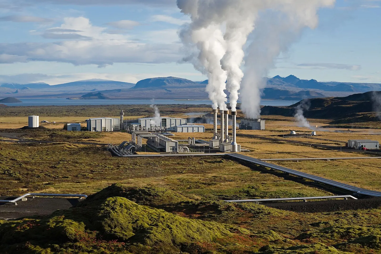
Geological formations and engineered underground spaces can hold hydrogen, compressed air, heat, cold and water at a scale no surface tank can match — often for weeks or a whole season. Salt caverns, rock caverns, depleted gas fields, aquifers, borehole fields and old mines each suit a different energy form. BARREL brings geology, drilling, cavern engineering, surface plant and grid connection together in one project, working with specialist subsurface partners.
GGeology
Salt, rock, aquifer, mine
WWells
Drilling, completion, integrity
SSurface
Compression, heat, power, controls
- Duration range
- Weeks–seasons
- Energy scale
- GWh–TWh
- Typical large salt cavern
- ≈ 500,000 m³
- Asset life
- 30–50+ yrs
- Land footprint
- Very low
Section 01
Underground Storage — Overview
Underground storage uses the earth itself as the container. The rock gives pressure containment, insulation and a natural safety distance; on the surface you see only wellheads and a compact plant of compressors, pumps, heat exchangers and electrical equipment.
Natural gas has been stored underground for about a century, and crude oil and LPG in rock caverns for decades — including India's strategic petroleum reserves. The same skills now serve hydrogen, compressed air, seasonal heat and cold, and pumped hydro or gravity storage in disused mines.
Underground stores are the main option for long-duration and seasonal storage: they hold far more energy per rupee of container than any steel tank, but each depends on finding the right geology and proving it with surveys and test wells.
1.1Formations and what they store
| Formation | Stores | Strength | Maturity |
|---|---|---|---|
| Salt caverns | Hydrogen, compressed air, natural gas, liquids | Tight, self-sealing, fast cycling | Commercial (gas; H₂ in UK and US since 1970s–80s) |
| Lined rock caverns (LRC) | Natural gas, hydrogen at high pressure | Works in hard rock where there is no salt | Demonstration (Sweden) |
| Unlined rock caverns | Crude oil, LPG, products | Very large volume, water-curtain sealing | Commercial (India SPR, LPG caverns) |
| Depleted gas / oil fields | Natural gas; hydrogen studied | Very large volume, proven seal | Commercial for gas; H₂ pilots |
| Aquifers (ATES) | Warm and cold groundwater | Seasonal heating and cooling | Commercial (Europe) |
| Borehole fields (BTES) | Heat in rock or soil | Works almost anywhere | Commercial |
| Abandoned mines | Water (pumped hydro), weights, air, mine-water heat | Reuses existing shafts and voids | Pilots and studies |
1.2Why go underground
01
Scale
One salt cavern can hold over 100 GWh of hydrogen energy — more than the largest battery parks in the world.
02
Cost per kWh
The rock is the vessel, so the cost of extra storage capacity is very low once wells and caverns exist.
03
Safety
Hundreds of metres of rock separate the stored medium from people and buildings; fire and blast risks sit mainly in the surface plant.
04
Land
A few hectares on the surface for a store that would need a large tank farm above ground.
1.3What it is used for
- Seasonal hydrogen buffer
- Hydrogen to power for firm supply
- Compressed air energy storage
- Strategic oil and gas reserves
- District heating and cooling
- Campus and hospital cooling
- Pumped hydro without a new valley
- Mine closure and reuse
- Industrial waste-heat storage
Suitability is always site-specific and must be proven by surveys and test wells. Figures and maturity notes on this page are typical or indicative ranges from public literature, not project guarantees.
Section 02
How Underground Storage Works
There are three ways the ground stores energy: as compressed gas (hydrogen, air, natural gas) held at pressure in a sealed space; as heat or cold in water or rock; and as height — water or weights raised from deep in a mine.
In every case the surface plant does the energy conversion. Compressors, pumps and heat pumps charge the store; turbines, expanders, fuel cells or heat exchangers discharge it.
2.1Three storage principles
Pressure (gas storage)
4- Gas is compressed and injected through a well
- Pressure swings between a maximum and a minimum
- Gas below the minimum stays as cushion gas
- Energy is in the gas itself (hydrogen) or in its pressure (air)
Temperature (thermal storage)
4- Warm or chilled water is pumped into an aquifer, or heat is passed into rock through borehole loops
- The ground holds it for weeks or months
- The flow is reversed in the opposite season
- Heat pumps or chillers lift the temperature as needed
Height (gravity storage)
4- Water drops from a surface pond into a mine void through turbines
- Or heavy weights are lowered down a shaft
- Pumping or lifting recharges the store
- Energy = mass × gravity × height
2.2Hydrogen cavern: one cycle
- Surplus solar or wind
- Electrolyser makes H₂
- Compressor to 60–200 bar
- Injection well
- Salt cavern stores weeks of output
- Withdrawal, drying and purification
- Fuel cell, turbine or industrial user
2.3Compressed air: one cycle
- Off-peak power
- Compressor train with intercooling
- Air into cavern at 40–80 bar
- Heat stored (adiabatic) or wasted (diabatic)
- Air reheated
- Expander turbine
- Peak power to grid
2.4Aquifer thermal: one year
- Winter: cold well water chilled further
- Stored in the cold well
- Summer: cold water cools the building
- Warmed water returns to the warm well
- Winter: warm water feeds a heat pump
Pressure and temperature ranges shown are typical operating windows reported for existing plants; each site sets its own limits from rock-mechanics studies.
Section 03
Salt Caverns
Caverns are washed out of thick salt layers or salt domes by solution mining: fresh water is pumped down a well, dissolves the salt and returns as brine, leaving a sealed cavity that can be hundreds of metres tall and tens of metres wide.
Salt creeps slowly and heals its own cracks, and it is almost impermeable to gas, so caverns hold hydrogen and compressed air with very low leakage and can be cycled many times a year — far more often than porous reservoirs.
3.1Typical salt cavern parameters
| Parameter | Typical range | Comment |
|---|---|---|
| Depth of cavern roof | 500–1,500 m | Deeper allows higher pressure but more creep |
| Geometric volume | 100,000–1,000,000 m³ | Around 500,000 m³ is common for new caverns |
| Operating pressure | ≈ 0.3–0.8 of overburden pressure | Often about 60–180 bar for hydrogen |
| Cushion gas share | ≈ 25–35% of total gas | Stays in the cavern to keep it stable |
| Working hydrogen per cavern | ≈ 2,000–6,000 t | ≈ 70–200 GWh (LHV) |
| Leaching time | ≈ 2–4 years per cavern | Depends on water supply and brine disposal |
| Water used for leaching | ≈ 7–10 m³ per m³ of cavity | Returned as saturated brine |
| Cycles per year | Several to dozens | Rate limited by pressure change per day |
3.2Developing a cavern
- 1Regional salt mapping from old wells and seismic surveys
- 2Exploration well, salt cores and laboratory creep tests
- 3Rock-mechanics modelling and cavern shape design
- 4Drilling and cementing the access well with gas-tight casing
- 5Solution mining with controlled water injection and blanket fluid
- 6Brine treatment, sale or disposal
- 7Sonar surveys of the cavern shape during and after leaching
- 8Mechanical integrity test of the well and cavern
- 9Debrining and first fill with gas
- 10Commissioning and first pressure cycles
3.3Well-known reference sites
01
HydrogenTeesside, UK
Three small salt caverns have stored hydrogen for the chemical industry since the early 1970s.
02
HydrogenUS Gulf Coast
Salt-dome caverns in Texas (for example Clemens Dome, in service since the 1980s) supply refinery and pipeline hydrogen.
03
Compressed airHuntorf and McIntosh
The two long-running compressed-air plants, both using salt caverns (see the CAES tab).
3.4India and the region
- India has limited known thick salt formations; the evaporite layers of the Nagaur–Ganganagar basin in Rajasthan are the main area studied.
- Salt depth, thickness, purity and water availability for leaching in a dry region all need investigation before any project.
- Where salt is absent, lined rock caverns, depleted fields, pipeline line-pack and above-ground vessels are compared instead.
Cavern figures are typical ranges from public literature on gas and hydrogen storage; every cavern is designed for its own depth, salt quality and stress field.
Section 04
Underground Compressed Air Energy Storage
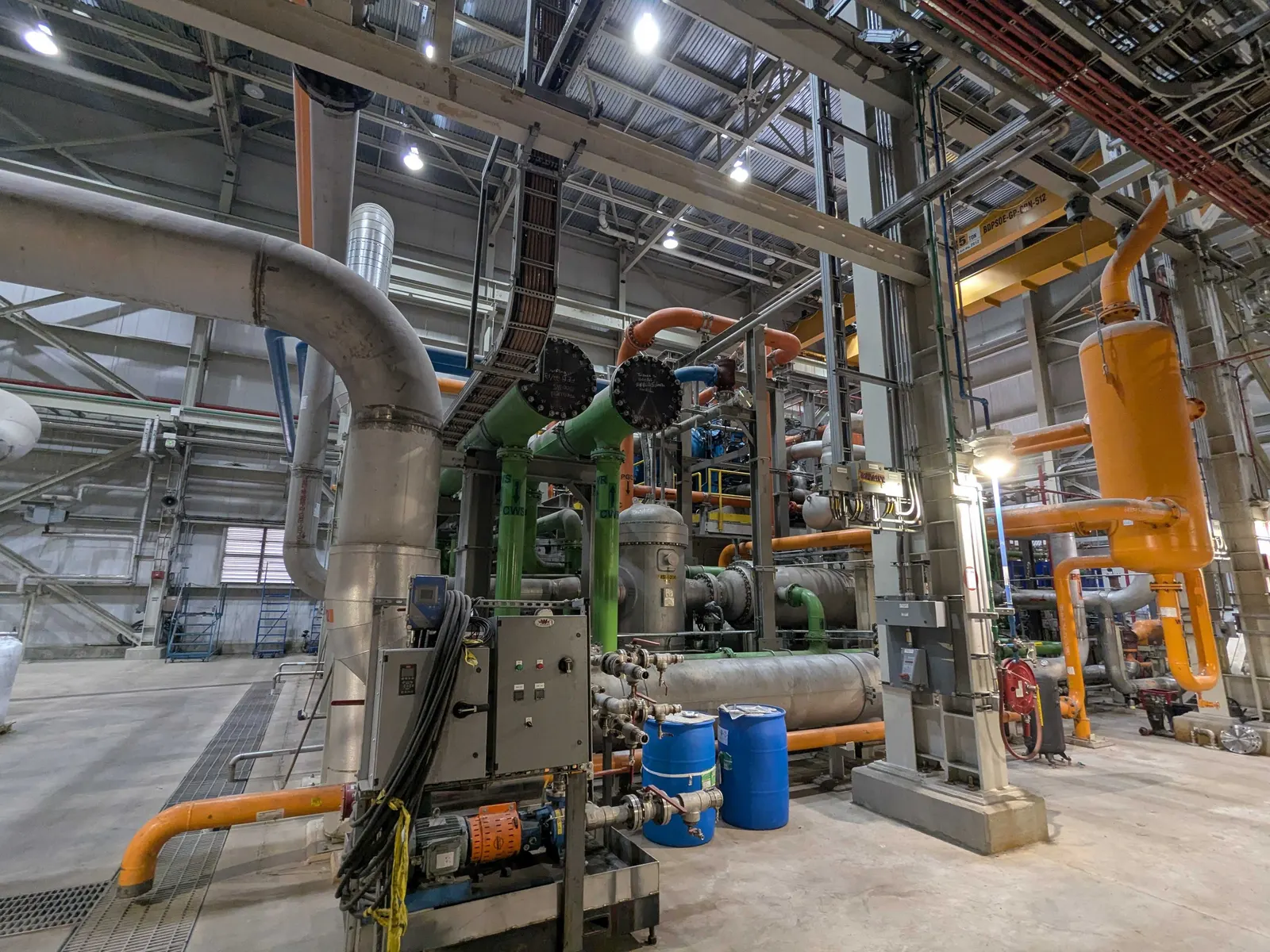
CAES uses cheap electricity to compress air into a cavern and later releases it through a turbine. In the classic diabatic design the heat of compression is thrown away and natural gas reheats the air before the turbine; newer adiabatic designs store the heat and reuse it, with no fuel.
Because the cavern is large and cheap, CAES suits several hours to a few days of storage at 100 MW scale and above.
4.1Reference plants
| Plant | Year | Output | Store | Notes |
|---|---|---|---|---|
| Huntorf, Germany | 1978 | 290 MW (later uprated to about 320 MW) | Two salt caverns, ≈ 310,000 m³ total | First commercial CAES; diabatic, gas-fired reheat |
| McIntosh, Alabama, USA | 1991 | 110 MW for up to about 26 h | One salt cavern, ≈ 560,000 m³ | Diabatic with recuperator for better efficiency |
4.2CAES variants
Diabatic
4- Heat of compression rejected
- Gas burnt to reheat air
- Proven since 1978
- Round-trip roughly 42–55% (fuel counted separately)
Adiabatic (A-CAES)
4- Heat stored in a thermal store
- No fuel
- Round-trip roughly 55–70% (design studies)
- Large first plants under development abroad
Isothermal / hydraulic
4- Near-constant temperature by spray or water
- Water-compensated caverns keep pressure steady
- Pilot and demonstration stage
- Can suit hard-rock caverns and mines
4.3Cavern requirements
- Pressure window typically about 40–80 bar
- Salt preferred; hard-rock caverns and porous rock studied
- Fast daily cycling means careful limits on pressure change rate
- Moisture and corrosion control in wells and turbines
- Volume of the order of 2–6 kWh of electricity per m³ in existing diabatic plants
- Constant-pressure designs use a water column from a surface pond
Efficiencies and energy densities are indicative figures from public literature on Huntorf, McIntosh and design studies; actual values depend on design and operation.
Section 05
Depleted Gas Fields and Porous Rock
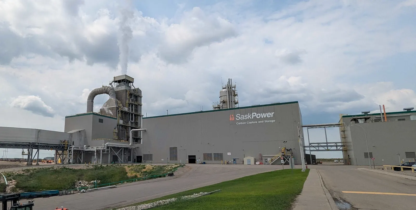
Porous rock that once held oil or gas has already proved it can trap gas for millions of years under a cap rock. Re-used as a store, it offers very large volumes — enough for seasonal balancing of a whole region.
Natural gas has been stored this way worldwide for decades. Hydrogen is harder: it is lighter, diffuses more easily, can react with minerals and can be consumed by microbes in the rock, so pilots are still testing how much can be recovered and how pure it comes back.
5.1Strengths and open questions
Strengths
4- Proven seal and known geology from production years
- Existing wells and data may be reusable
- Very large working volume (TWh-scale for big fields)
- Natural fit for seasonal storage
Open questions for hydrogen
5- Mixing with residual gas lowers purity
- Microbial activity can turn H₂ into methane or H₂S
- Large cushion gas — often 40–60% of total
- Slower injection and withdrawal than salt caverns
- Old well integrity must be checked for hydrogen
5.2Pilots and studies
01
Hydrogen in a depleted gas field
Pilots in Austria and elsewhere in Europe have injected hydrogen or hydrogen-rich gas into small depleted reservoirs to study recovery and purity.
02
Town-gas history
Aquifers in Europe once stored town gas containing about half hydrogen, giving early data on hydrogen behaviour underground.
03
Underground methanation
Some research deliberately lets microbes turn hydrogen and CO₂ into methane in the reservoir.
5.3India context
- India's mature oil and gas basins (for example Cambay, Assam–Arakan and Krishna–Godavari) contain depleted fields that could be screened for gas or hydrogen storage.
- Field data are held by operators and the Directorate General of Hydrocarbons; access and licensing would be part of any study.
- Porous-rock storage could also pair with carbon capture work, which uses similar reservoir skills.
Cushion-gas shares and recovery figures for hydrogen in porous rock are still uncertain and come from pilots and modelling; treat them as indicative.
Section 06
Lined and Unlined Rock Caverns
Where there is no salt, caverns can be excavated in hard rock such as granite or gneiss by drill-and-blast, like a large tunnel. Two families exist: unlined caverns kept below the water table, where groundwater pressure holds liquids in, and lined rock caverns with a thin steel liner backed by concrete for high-pressure gas.
India already has a strong precedent: the strategic petroleum reserves built by Indian Strategic Petroleum Reserves Limited (ISPRL) are unlined rock caverns holding crude oil underground.
6.1India's strategic petroleum reserve caverns
| Site | State | Capacity (crude) | Type |
|---|---|---|---|
| Visakhapatnam | Andhra Pradesh | 1.33 million tonnes | Unlined rock cavern |
| Mangaluru | Karnataka | 1.5 million tonnes | Unlined rock cavern |
| Padur | Karnataka | 2.5 million tonnes | Unlined rock cavern |
| Total (Phase I) | 5.33 million tonnes | Further sites announced for Phase II |
6.2Two kinds of rock cavern
Unlined (hydrodynamic containment)
5- Cavern sits below the natural water table
- Water curtain boreholes above keep rock saturated
- Water pressure stops oil or LPG escaping
- Used for crude, products and LPG
- Low pressure; not suited to hydrogen
Lined rock cavern (LRC)
5- Thin steel liner, concrete backing, rock carries the load
- Pressures up to about 200–250 bar
- Shallower (100–200 m) than salt caverns
- Natural gas demonstration at Skallen, Sweden, since early 2000s
- Small hydrogen pilot at Luleå, Sweden, since 2022
6.3Design points
- Rock mass quality, joints and stress measured by boreholes and test adits
- Groundwater flow and water-curtain design
- Liner material checked for hydrogen embrittlement
- Uplift safety: rock cover must resist maximum pressure
- Excavation spoil handling and reuse
- Tunnel access, shafts and ventilation during construction
Capacities are as published by ISPRL for Phase I; lined-rock-cavern pressures are from Swedish demonstration reports. Rock caverns for hydrogen remain at demonstration stage worldwide.
Section 07
Aquifer Thermal Energy Storage (ATES)
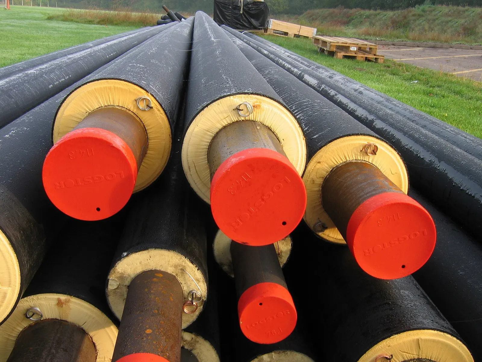
ATES uses a natural water-bearing sand or gravel layer as a seasonal store. Pairs of wells pump groundwater in opposite directions: in summer, cold water from the cold well cools buildings and is returned warmer to the warm well; in winter the flow reverses and the stored warmth feeds heat pumps.
The Netherlands has thousands of ATES systems serving offices, hospitals and campuses. In India, where cooling dominates, the cold side and waste-heat storage are the main interest.
7.1Typical ATES parameters
| Parameter | Typical range |
|---|---|
| Aquifer depth | 20–300 m (low-temperature systems) |
| Well flow | 20–300 m³/h per well |
| Temperature in the store | Cold well ≈ 5–10 °C, warm well ≈ 15–25 °C (low-temperature); high-temperature ATES up to 50–90 °C |
| Thermal power per doublet | ≈ 0.5–3 MW(th) |
| Recovery efficiency | ≈ 60–90% when flows are balanced |
| Well spacing | Often 100–200 m between warm and cold wells |
7.2What a site needs
Ground
3- Permeable aquifer of adequate thickness
- Low natural groundwater flow
- Water chemistry that will not clog wells
Demand
3- Both heating and cooling, or cooling plus a heat sink
- Balanced energy over the year
- Large buildings, campuses, data centres, districts
Permits
3- Groundwater authority approval
- Protection of drinking-water aquifers
- Monitoring of temperature and water quality
7.3India considerations
- Central Ground Water Authority and state groundwater rules apply to any abstraction and reinjection.
- Over-exploited aquifers in many districts call for closed balance: every litre pumped is reinjected.
- Alluvial aquifers of the Indo-Gangetic plain may suit ATES; hard-rock areas of the Deccan usually suit borehole fields better.
ATES figures are typical values from European practice and literature; Indian aquifer behaviour must be confirmed by pumping tests.
Section 08
Borehole Thermal Energy Storage (BTES)
BTES passes water through closed plastic loops in dozens to hundreds of boreholes drilled close together. Heat flows into the surrounding rock or soil and is recovered months later. No groundwater is pumped, so permits are simpler and it works almost anywhere drilling is possible.
The same boreholes, used every day rather than seasonally, are the ground loops of a ground-source heat pump.
8.1Typical BTES parameters
| Parameter | Typical range |
|---|---|
| Borehole depth | 30–300 m |
| Borehole spacing | ≈ 2–5 m in a compact field |
| Number of boreholes | Dozens to several hundred |
| Storage temperature | Up to about 60–90 °C for seasonal solar heat |
| Rock volumetric heat capacity | ≈ 2.0–2.5 MJ/m³·K |
| Seasonal efficiency | ≈ 40–70%, better for larger, well-insulated fields |
8.2Reference and uses
01
ReferenceDrake Landing, Canada
A community of 52 homes in Alberta stores summer solar heat in a field of 144 boreholes about 35 m deep, covering most of its winter space heating.
02
Industrial waste heat
Heat from furnaces, compressors or data centres stored for later process or space heating.
03
Cooling-led use
In hot climates the field can be pre-cooled at night or in winter to serve daytime or summer cooling.
8.3Design steps
- Thermal response test on a trial borehole
- Ground model of conductivity and heat capacity
- Field layout: depth, spacing, series and parallel loops
- Top insulation and edge losses
- Heat pump and buffer tank selection
- Multi-year simulation of field temperature
Drake Landing figures are as reported publicly by the project; parameter ranges are typical literature values.
Section 09
Abandoned Mines for Energy Storage
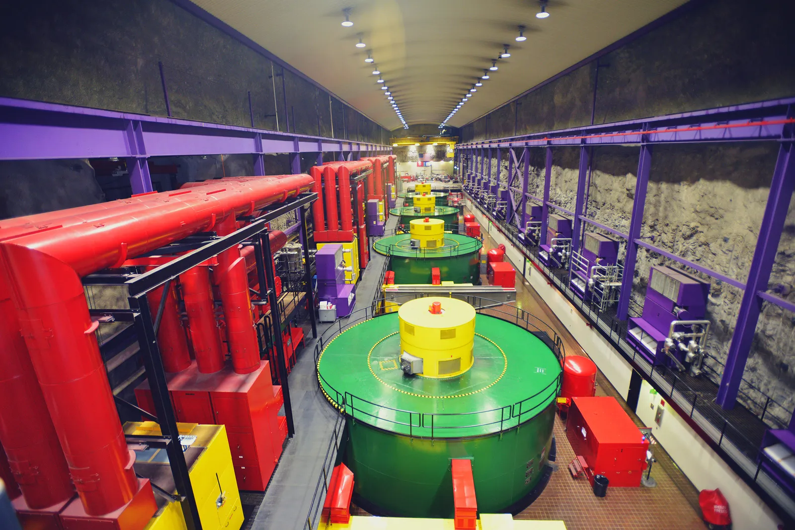
A closed mine already has what is most expensive to build: deep shafts, tunnels and voids. These can be turned into the lower reservoir of a pumped hydro plant, a shaft for heavy weights, a compressed-air store or a heat source for heat pumps.
For coal and metal regions facing mine closure, this offers a second life for the site, the grid connection and local skills.
9.1Options for a mine
01
Underground pumped hydro
A mine void or new cavern as the lower reservoir and a surface pond as the upper one — no dam in a river valley. Heads of several hundred metres are possible.
02
Shaft gravity storage
Heavy weights raised and lowered in a deep vertical shaft by winches; fast response, modest energy per shaft.
03
Compressed air
Sealed galleries or lined drifts as a pressure store where the rock is sound and the mine is tight.
04
Mine-water heat
Flooded workings as a large, steady-temperature water body for heat pumps and seasonal storage.
05
Open-pit pumped hydro
A worked-out open-cast pit as one reservoir, with a second pond on the overburden dump or higher ground.
06
Hybrid site
Solar on dumps and tailings, storage in the mine, and the existing substation for export.
9.2Screening a mine
| Check | Why it matters |
|---|---|
| Depth and void volume | Sets energy (head × volume) and duration |
| Rock stability and support | Old workings may collapse under water-level swings |
| Water chemistry | Acid mine drainage attacks turbines and pipes |
| Groundwater links | Must not pollute or drain nearby aquifers |
| Shaft condition | Reuse cuts cost; repair may be needed |
| Grid and land | Existing connection and surface land for ponds or plant |
| Ownership and closure plan | Who holds liability, and how storage fits the mine closure plan |
9.3India context
- India has many closed and soon-to-close coal mines; reusing them for pumped storage and solar is being explored under the Ministry of Coal's mine-closure and just-transition work.
- Open-cast pits in Jharkhand, Odisha, Chhattisgarh and Madhya Pradesh are among those discussed for pumped storage.
- Mine safety (DGMS) and state mining approvals apply alongside power-sector rules.
Mine storage worldwide is mostly at study and pilot stage; studies in Germany and Finland have looked at underground pumped hydro and shaft gravity storage in former mines.
Section 10
System Types and Technical Architecture
Every underground store has three layers: the subsurface store (cavern, reservoir, aquifer, borehole field or mine), the wells or shafts that connect it to the surface, and the surface plant that converts energy in and out.
The configuration depends on what is stored and who uses it — a hydrogen hub, a power plant, a district heating network or an industrial site.
10.1Common configurations
| Configuration | Store | Charge | Discharge |
|---|---|---|---|
| Power-to-hydrogen-to-power | Salt or rock cavern | Electrolyser + compressor | Gas turbine or fuel cell |
| Hydrogen hub buffer | Salt cavern | Electrolysers and pipeline | Steel, fertiliser, refinery users |
| Diabatic CAES | Salt cavern | Motor-driven compressors | Gas-fired expander turbine |
| Adiabatic CAES | Cavern + heat store | Compressors, heat recovered | Air reheated from heat store |
| ATES campus | Aquifer doublet | Chillers / heat pumps | Direct cooling, heat pumps |
| BTES district heat | Borehole field | Solar thermal or waste heat | District heating via heat pumps |
| Mine pumped hydro | Mine void + surface pond | Reversible pump-turbines | Same machines as turbines |
10.2Main components
Subsurface
4- Cavern, reservoir, aquifer or void
- Cap rock or seal
- Cushion gas or water
- Monitoring wells
Wells and wellheads
5- Casing strings and cement
- Production tubing and packers
- Subsurface safety valve
- Wellhead and Christmas tree
- Downhole gauges
Surface plant
6- Compressors and coolers
- Dehydration and purification
- Heat exchangers and thermal stores
- Pumps, turbines, expanders
- Flare or vent stack
- Electrical and control systems
10.3Hydrogen surface plant in detail
- Inlet filters and metering
- Reciprocating or diaphragm compressors, often in stages
- Intercoolers and after-coolers
- Glycol or adsorption dryers (hydrogen picks up water from salt caverns)
- Purification (pressure-swing adsorption) for fuel-cell grade
- Pressure letdown with heating to avoid freezing
- Emergency shutdown valves and blowdown
- Gas detection, fire and gas system
Component lists are typical of gas-storage practice; each project's process design sets the final equipment.
Section 11
Power Conversion, Controls and Grid Integration
Underground storage plants are large electrical loads when charging and, for CAES, hydrogen-to-power and mine pumped hydro, large generators when discharging. The electrical design, controls and grid connection are as important as the geology.
11.1Electrical systems
High voltage
4- Switchyard and step-up transformers
- Bay protection and metering
- Line connection to state grid or ISTS
- Reactive power support
Drives and machines
4- Large compressor motors with variable-speed drives
- Synchronous or variable-speed generators
- Reversible pump-turbines for mine hydro
- Rectifiers for electrolysers
Auxiliaries
4- Medium- and low-voltage switchgear
- Emergency diesel or battery supply
- UPS for controls and safety systems
- Earthing and lightning protection
11.2Controls: EMS, SCADA and safety
Energy management (EMS)
4- Schedules charge and discharge against tariffs and dispatch
- Respects pressure-change limits of the cavern
- Forecasts renewable surplus
- Coordinates with batteries for fast response
SCADA and DCS
4- Wellhead, compressor and turbine control
- Historian for pressure, temperature, flow
- Alarm management
- Remote monitoring centre link
Safety instrumented systems
4- Emergency shutdown on high pressure or gas leak
- Subsurface safety valve closure
- Fire and gas detection
- Independent of the process control system
11.3Grid services by type
| Type | Ramp / response | Typical role |
|---|---|---|
| Mine pumped hydro | Minutes | Peak shifting, reserves, inertia |
| CAES | Minutes | Daily shifting, reserves |
| Hydrogen cavern + turbine | Minutes to start | Weekly and seasonal firm power |
| Hydrogen cavern + industry | Continuous | Keeps a steel or ammonia plant running when renewables dip |
| ATES / BTES | Hours | Cuts summer cooling peak, shifts thermal load |
11.4Grid connection in India
- Connectivity follows CEA technical standards for grid connection and CERC or state connectivity regulations.
- Large plants may connect to ISTS; smaller thermal systems sit behind the meter of the user.
- Firm and dispatchable renewable (FDRE) and round-the-clock (RTC) tenders are the main market route for long-duration storage paired with solar and wind.
Section 12
Sizing and Design Calculations
First-pass sizing for underground storage uses a few physical relations: how much gas a volume holds at a given pressure, how much heat water or rock holds per degree, and how much energy water or weights hold per metre of height.
The worked examples and the live estimator below are for early screening only. Detailed design uses real-gas equations of state, reservoir simulation and rock-mechanics models.
12.1Gas held in a cavern
Mass of gas at pressure
m = p × V × M ÷ (Z × R × T)
500,000 m³ at 180 bar, 45 °C, Z ≈ 1.1 → ≈ 12.5 kg/m³ → ≈ 6,240 t of H₂ in the full cavern
The real-gas law gives the mass of gas in a fixed volume. Hydrogen is lighter than ideal at high pressure, so Z is above 1 (about 1.05–1.15 in typical cavern conditions, higher at very high pressure).
| Symbol | Meaning |
|---|---|
| m | Mass of gas, kg |
| p | Pressure, Pa (1 bar = 100,000 Pa) |
| V | Cavern geometric volume, m³ |
| M | Molar mass, kg/mol (H₂ = 0.002016; air ≈ 0.029) |
| Z | Compressibility factor (real-gas correction) |
| R | Gas constant, 8.314 J/mol·K |
| T | Gas temperature, K (°C + 273.15) |
12.2Working gas and energy
Usable hydrogen between pressure limits
Working gas = m(p max) − m(p min); E = working gas × 33.3 kWh/kg
At 60 bar, Z ≈ 1.04 → ≈ 4.4 kg/m³ → cushion ≈ 2,200 t; working ≈ 4,040 t ≈ 135 GWh (LHV)
Only the gas between the maximum and minimum pressure can be used; the rest stays as cushion gas to support the cavern walls. Multiply the working hydrogen by its lower heating value to get stored chemical energy.
| Symbol | Meaning |
|---|---|
| p max | Highest allowed pressure (from rock mechanics) |
| p min | Lowest allowed pressure (to limit creep and closure) |
| 33.3 kWh/kg | Lower heating value of hydrogen |
| E | Stored energy, kWh (÷ 1,000,000 for GWh) |
12.3Live estimator
Enter a cavern volume (m³), the maximum and minimum operating pressures (bar) and the gas temperature (°C). The estimator uses the real-gas law with an approximate hydrogen compressibility factor (Z ≈ 1.04–1.15, rising with pressure) to give the working hydrogen in tonnes, the cushion gas left at minimum pressure in tonnes, and the stored energy in GWh at hydrogen's lower heating value of 33.3 kWh/kg. It is a screening figure; real caverns need site rock-mechanics limits and an exact equation of state.
Estimate
- Working gas
- 3,958 t H₂
- Energy (LHV)
- 131.8 GWh
- Cushion gas (stays in)
- 2,203 t H₂
- Working-gas share
- 64 %
Real-gas estimate with a simple compressibility fit (Z ≈ 1.04–1.15). Allowed pressures come from depth and rock mechanics; confirm with a site study. Preliminary screening only; BARREL confirms any figure with a site study.
12.4Heat or cold in water or rock
Sensible heat stored
Q = V × ρc × ΔT × η
ATES: 300,000 m³ of water × 1.16 kWh/m³·K × 6 K × 0.8 ≈ 1,670 MWh(th) per season
Water stores about 1.16 kWh per m³ per degree; rock about 0.55–0.70 kWh per m³ per degree. The recovery factor η covers heat lost to the surroundings. The same relation with flow instead of volume gives thermal power: 100 m³/h × 1.16 × 6 K ≈ 0.7 MW(th).
| Symbol | Meaning |
|---|---|
| Q | Recovered heat or cold, kWh(th) |
| V | Water pumped per season, or rock volume, m³ |
| ρc | Volumetric heat capacity, kWh/m³·K |
| ΔT | Temperature swing, K |
| η | Recovery efficiency (ATES ≈ 0.6–0.9, BTES ≈ 0.4–0.7) |
12.5Mine pumped hydro and shaft gravity
Energy from height
E = ρ × g × h × V × η ÷ 3,600,000,000 (MWh)
1,000,000 m³ of water × 600 m head × 0.75 ≈ 1,230 MWh; a 1,000 t weight in a 1,000 m shaft × 0.85 ≈ 2.3 MWh
Water stored in a mine void at depth h below a surface pond gives potential energy. For weights, replace ρ × V by the mass in kg. Deep mines give high head, so a small volume of water stores a lot of energy.
| Symbol | Meaning |
|---|---|
| ρ | Water density, 1,000 kg/m³ |
| g | Gravity, 9.81 m/s² |
| h | Net head or lift height, m |
| V | Usable water volume, m³ |
| η | Round-trip efficiency (pumped hydro ≈ 0.70–0.80) |
12.6Rules of thumb for screening
| Item | Indicative value |
|---|---|
| Max cavern pressure | ≈ 0.8 × overburden at the cavern roof (≈ 0.023 bar/m × depth × 0.8) |
| Min cavern pressure | ≈ 0.25–0.35 × overburden |
| Pressure change rate | Often limited to about 10 bar per day in salt caverns |
| Diabatic CAES cavern | ≈ 2–6 kWh(e) per m³ |
| Water for leaching | ≈ 7–10 m³ per m³ of cavern |
| Electrolyser energy | ≈ 50–55 kWh per kg H₂ |
Worked examples use rounded inputs and simplified Z values; results are indicative only. Final design limits come from site-specific tests and modelling.
Section 13
Engineering Deliverables Register
An underground storage project produces a long list of studies and documents across geology, wells, process plant and electrical systems. The register below shows the main items BARREL and its partners would prepare or coordinate.
13.1Main deliverables by stage
| Stage | Deliverable | Discipline |
|---|---|---|
| Screening | Desk study of geology, demand and grid | Geology / power |
| Screening | Long list and ranking of candidate sites | Multi-discipline |
| Feasibility | Geophysical survey report and interpretation | Geophysics |
| Feasibility | Exploration well programme and core-test results | Drilling / geology |
| Feasibility | Geomechanical model and storage capacity estimate | Rock mechanics |
| Feasibility | Hydrogeological model and pumping-test report (ATES) | Hydrogeology |
| Feasibility | Thermal response test and field simulation (BTES) | Thermal |
| Pre-FEED | Concept design, block-flow diagram, cost estimate | Process / cost |
| FEED | Cavern or well design basis and well schematics | Wells |
| FEED | Process and instrumentation diagrams (P&IDs) | Process |
| FEED | Hazard identification (HAZID), HAZOP, SIL study | Safety |
| FEED | Single-line diagram and grid study | Electrical |
| Detailed | Equipment data sheets and specifications | All |
| Detailed | Civil, structural and layout drawings | Civil |
| Approvals | Environmental impact assessment and management plan | Environment |
| Construction | Leaching programme and sonar survey plan | Cavern |
| Handover | Commissioning reports, integrity test records, O&M manuals | All |
13.2Models kept through the asset life
- 3D geological model
- Geomechanical model
- Reservoir / cavern thermodynamic model
- Groundwater model
- Process simulation
- Grid model
- Digital twin
The register is illustrative; scope varies by technology and by what the client or other contractors provide.
Section 14
Site Selection and Feasibility
Site selection for underground storage starts with the rock, not the land. A good site has the right formation at the right depth, close enough to the energy source, the users and the grid.
14.1Screening criteria
| Technology | Key geological criteria | Key surface criteria |
|---|---|---|
| Salt cavern | Salt ≥ 200 m thick (bedded) or a dome; depth ≈ 500–1,500 m; few impurity layers | Water for leaching; brine outlet; H₂ users or grid |
| Lined rock cavern | Sound hard rock at 100–200 m; low fracturing | Access tunnel portal; spoil area |
| Unlined rock cavern | Hard rock below stable water table | Port or pipeline for liquids |
| Depleted field | Known seal, good permeability, well records | Pipeline links, field licence |
| ATES | Permeable aquifer 20–300 m, slow groundwater flow | Balanced heating and cooling demand |
| BTES | Drillable ground, moderate conductivity, little groundwater flow | Heat source (solar, waste heat) and heat users nearby |
| Mine storage | Stable voids, depth, tight rock, acceptable water quality | Surface pond site, grid connection |
14.2Feasibility path
- 1Define the energy to store, duration and users
- 2Desk study of geological maps, old wells and mine records
- 3Shortlist sites and engage landowners and authorities
- 4Surface geophysics (seismic, gravity, resistivity)
- 5Exploration or test well, cores and logs
- 6Laboratory tests and models
- 7Capacity estimate, concept design and cost
- 8Go / no-go decision for FEED and approvals
14.3Reducing subsurface risk early
- Spend on data before spending on plant
- Use existing well and mine data where possible
- Plan stage gates with clear stop criteria
- Compare against above-ground alternatives at each gate
- Seek government geological data (Geological Survey of India, DGH data repository)
- Keep the community informed from the first survey
Section 15
Turnkey EPC and Supply Chain
Underground storage EPC combines two worlds: subsurface contracting (drilling, leaching, tunnelling) and surface plant construction (compressors, process, electrical). BARREL can act as the single point of responsibility for the surface plant and integration, working with specialist drilling and cavern partners.
15.1Project phases
- 1Screening and feasibility (6–18 months)
- 2Exploration and test wells (1–2 years)
- 3FEED and approvals (1–2 years)
- 4Drilling and cavern leaching, or excavation (2–4 years for salt caverns)
- 5Surface plant construction in parallel
- 6Integrity testing, first fill and commissioning
- 7Handover, O&M and long-term monitoring
15.2Typical work packages
Subsurface
5- Drilling and well completion
- Solution mining and brine handling
- Rock excavation and lining
- Borehole field drilling
- Mine rehabilitation
Process plant
4- Compressors and coolers
- Dehydration and purification
- Thermal stores and heat exchangers
- Piping, valves, flare
Electrical and civil
5- Substation and grid line
- Motors, drives, generators
- Control buildings
- Roads, ponds, foundations
- Fire-fighting systems
15.3Equipment and supply chain in India
| Item | India capability | Comment |
|---|---|---|
| Drilling rigs and services | Established (oil, gas, mining sectors) | Deep salt drilling experience limited |
| Casing, tubing, line pipe | Manufactured in India | Hydrogen-grade steel to be qualified |
| Wellheads and valves | Partly local, partly imported | API-certified sources |
| Rock tunnelling and caverns | Strong (hydro, metro, SPR projects) | SPR caverns built in India |
| Process compressors | Assembled locally; large hydrogen units often imported | Through OEM partners |
| Motors, transformers, switchgear | Strong domestic base | Make in India preferred |
| Heat pumps and chillers | Local assembly growing | Large industrial units often imported |
| HDPE ground loops | Manufactured in India | For BTES and ground-source fields |
15.4Delivery models
01
EPC lump sum (surface)
Fixed price for the surface plant once the subsurface is proven.
02
EPCM
BARREL manages specialist contractors for wells, caverns and plant on the owner's behalf.
03
Phased alliance
Stage-gated contract that moves from studies to construction as risk falls.
Durations are indicative; salt-cavern leaching time depends strongly on water supply and brine disposal capacity.
Section 16
Testing and Commissioning
Before any gas or heat goes underground, the wells and the store must be proven tight and stable. Commissioning then brings the surface plant on line step by step, with the store filled slowly to its working pressure.
16.1Key tests
| Test | What it proves |
|---|---|
| Cement bond and casing logs | Cement seals the casing to the rock |
| Mechanical integrity test (MIT) | Well and cavern hold pressure with negligible leak |
| Sonar survey | Cavern shape and volume match design |
| Pressure build-up test | Reservoir or aquifer behaves as modelled |
| Pumping and injection test (ATES) | Well yield, clogging risk, water chemistry |
| Thermal response test (BTES) | Ground conductivity for field design |
| Liner leak test (LRC) | Steel liner and welds are gas-tight |
| Factory and site acceptance tests | Compressors, turbines, controls work as specified |
16.2Commissioning sequence
- 1Mechanical completion and punch-list closure
- 2Pre-commissioning: flushing, drying, purging with nitrogen
- 3Loop checks of instruments and safety systems
- 4Energising electrical systems
- 5Debrining and first gas fill at controlled rate
- 6Pressure cycling to working range
- 7Performance and reliability run
- 8Handover with records and baseline monitoring data
Test methods follow gas-storage practice (for example API and EN guidance); exact criteria are set in the project's test plan and by the approving authority.
Section 17
Operations, Maintenance and Digital Monitoring
Underground stores last decades, and their health is watched from the surface. Operations combine routine plant maintenance with continuous monitoring of pressure, temperature, ground movement and groundwater.
17.1Operations and maintenance tasks
Daily
4- Pressure and flow within limits
- Compressor and pump checks
- Gas detection and alarms
- Dispatch to schedule
Periodic
5- Wellhead valve testing
- Compressor overhauls
- Dryer and filter changes
- Heat-exchanger cleaning
- Water sampling (ATES, mines)
Multi-year
5- Repeat sonar surveys of caverns
- Repeat mechanical integrity tests
- Well workovers
- Subsidence surveys
- Model update and revalidation
17.2Digital and AI tools
01
Digital twin
Live model of cavern or reservoir pressure, temperature and gas inventory, matched to measured data.
02
Predictive maintenance
Vibration and performance analytics on compressors, pumps and turbines.
03
Optimised dispatch
Forecasts of renewable surplus and prices to plan injection and withdrawal.
04
Ground monitoring
Satellite radar (InSAR), microseismic sensors and fibre-optic cables to watch ground movement.
17.3Key indicators
- Working gas inventory and cushion gas
- Hydrogen purity at withdrawal
- Round-trip or recovery efficiency
- Cavern volume loss per year (creep)
- Thermal balance of aquifer over the years
- Availability of surface plant
Section 18
Safety and Risk
Underground storage has a good safety record in gas storage, but incidents worldwide have come from well failures, poorly understood geology and surface leaks. Most of the risk is managed through well integrity, conservative pressure limits and monitoring.
18.1Main hazards and controls
| Hazard | Control |
|---|---|
| Well leak or blowout | Multiple casing barriers, subsurface safety valve, well integrity programme |
| Hydrogen fire or explosion at surface | Hazardous-area design, gas detection, ventilation, separation distances |
| Cavern instability or collapse | Pressure limits from rock mechanics, sonar surveys, minimum pressure |
| Ground subsidence | Survey benchmarks, InSAR, conservative cavern spacing |
| Brine spill (leaching) | Lined ponds, pipeline monitoring, disposal permits |
| Groundwater contamination | Casing and cement design, monitoring wells |
| Induced seismicity | Microseismic monitoring and traffic-light rules |
| Mine flooding or acid water | Water treatment, rock support, closure plan |
18.2Hydrogen-specific points
- Steel selection to avoid hydrogen embrittlement
- Leak-tight connections; hydrogen flames are hard to see
- Odourless gas — detection must be instrumented
- Wide flammable range in air (about 4–75%)
- Purge and vent procedures with nitrogen
- Emergency response plan with local authorities
Hazard lists are typical of underground gas storage; each project's HAZID and HAZOP sets the actual risk register.
Section 19
Standards, Regulation and Approvals
Underground storage touches mining, petroleum, groundwater, pressure equipment, electricity and environmental law, so the approval path is planned at the start. India has no single rulebook for hydrogen or air storage underground yet; existing gas, mining and safety rules are applied with the authorities.
19.1International standards and guidance
| Reference | Covers |
|---|---|
| EN 1918 (parts 1–5) | Underground gas storage in aquifers, fields, salt caverns, rock caverns and surface facilities |
| API RP 1170 | Design and operation of solution-mined salt caverns for natural gas storage |
| API RP 1171 | Integrity of gas storage in depleted reservoirs and aquifers |
| ISO 16530 | Well integrity in the oil and gas industry |
| API 5CT / API 6A | Casing and tubing; wellhead equipment |
| ASME B31.12 | Hydrogen piping and pipelines |
| ISO 14687 | Hydrogen fuel quality |
| IEC 60079 series | Equipment for explosive atmospheres |
| NFPA 2 | Hydrogen technologies code |
| VDI 4640 | Thermal use of the underground (ground-source, BTES, ATES) |
19.2India: authorities and rules to check
Gas, pressure and safety
4- PESO — Petroleum and Explosives Safety Organisation (pressure vessels, compressed gases)
- OISD standards for oil and gas installations
- PNGRB for pipeline connections
- Factories Act and state factory inspectorate
Subsurface and mining
4- Directorate General of Hydrocarbons for petroleum fields and data
- State mining departments and mineral concession rules
- DGMS for mine safety
- Central Ground Water Authority and state groundwater boards
Power sector
4- Central Electricity Authority technical standards and safety regulations
- CERC and state commission regulations for connectivity and tariffs
- Ministry of Power storage guidelines
- MNRE schemes for green hydrogen
Environment and BIS
4- EIA Notification 2006 and environmental clearance
- State pollution control board consents
- BIS adoptions of IEC and ISO standards (IS/IEC 60079 and others)
- Coastal or forest clearances where they apply
Approval requirements differ by state and by stored medium; BARREL confirms them with the authorities for each site. Standard titles are summarised, not quoted.
Section 20
Environment and Circularity
Underground storage has a small surface footprint and long life, but each type has its own environmental issues — brine from leaching, groundwater temperature change, excavation spoil and the legacy of old mines.
20.1Environmental issues by type
Salt caverns
3- Large volumes of brine
- Brine to chemical industry, sea outfall or deep injection
- Fresh-water demand during leaching
Rock caverns and mines
3- Excavation spoil reused as aggregate
- Groundwater drawdown during construction
- Acid mine water treatment
ATES and BTES
3- Thermal plume in groundwater
- No net water use with balanced reinjection
- Leak-free loops and safe heat-transfer fluids
20.2Circular opportunities
01
Brine as product
Leaching brine can feed chlor-alkali or salt works instead of being discharged.
02
Second life for mines
Closed mines become storage assets, keeping jobs and grid connections in coal regions.
03
Reused oil and gas assets
Old fields, wells and pipelines find new use for gas or hydrogen storage.
20.3Climate benefits
- Lets more solar and wind be used instead of curtailed
- Seasonal heat and cold storage cuts electricity for cooling
- Hydrogen storage supports green steel and fertiliser
- Very small land use per unit of energy stored
Section 21
Commercial Models, Costs and Investment Risk
Underground storage has high up-front cost for exploration, wells and surface plant, but very low cost per extra unit of energy stored. It pays off when large amounts of energy must be held for long periods.
21.1Indicative cost drivers
| Item | Indicative range (public literature) | Comment |
|---|---|---|
| Salt cavern storage (container only) | ≈ US$0.2–2 per kWh of H₂ (LHV) | Lowest of any hydrogen store at large scale |
| Lined rock cavern for H₂ | Several times salt cavern cost | Demonstration stage |
| Above-ground pressure vessels | ≈ US$10–30+ per kWh of H₂ | For comparison |
| Diabatic CAES plant | ≈ US$1,000–1,500 per kW | Using an existing salt formation |
| ATES system | Payback often 3–10 years vs conventional chillers | Depends on balance and energy prices |
| Underground pumped hydro | Often higher per kW than surface pumped storage | Saved dam costs offset by underground works |
21.2Revenue and business models
Storage as a service
3- Capacity rented to hydrogen producers and users
- Fee per tonne stored or per injection/withdrawal right
- Like gas storage contracts
Power market
3- FDRE and RTC tender supply
- Energy shifting and peak sales
- Ancillary services and reserves
Thermal savings
3- Lower chiller and boiler energy bills
- Cooling-as-a-service contracts
- Reduced peak electricity demand charges
21.3Investment risks and mitigations
| Risk | Mitigation |
|---|---|
| Geology not as expected | Stage-gated spending, test wells before plant orders |
| Long development time | Early approvals plan; parallel surface works |
| Uncertain hydrogen demand | Anchor users, phased caverns |
| Regulatory gaps | Early engagement with PESO, CEA, MNRE and state bodies |
| Cost overrun underground | Experienced drilling partners, contingency, risk-sharing contract |
| Revenue certainty | Long-term storage contracts, tender-backed offtake |
Costs are indicative global ranges from public studies (for example IEA, NREL and national laboratory work) and vary widely with geology and scale. They are not BARREL quotations.
Section 22
India and Global Markets and Policy
Underground storage is growing worldwide alongside hydrogen and long-duration storage. Europe and the US lead in salt-cavern hydrogen and ATES; India's base is its strategic oil reserves, rock tunnelling skills and growing green hydrogen programme.
22.1Global picture
Europe
3- Large salt basins in Germany, Netherlands and UK
- Hydrogen cavern projects linked to hydrogen pipelines
- Thousands of ATES systems in the Netherlands
North America
3- Hydrogen salt caverns on the Gulf Coast
- McIntosh CAES since 1991
- Utah salt caverns for hydrogen-to-power under development
Asia and others
3- Strategic oil caverns in India, Korea, Japan and China
- China developing salt-cavern CAES
- Australia studying hydrogen caverns
22.2India policy drivers
- National Green Hydrogen Mission (2023), with a target of about 5 million tonnes of green hydrogen a year by 2030 — large hubs will need buffer storage.
- Energy storage obligations and storage guidelines from the Ministry of Power.
- FDRE and RTC renewable tenders that reward firm, long-duration supply.
- Viability gap funding for battery storage shows the policy route for other storage types.
- Strategic Petroleum Reserve Phase II expansion builds more rock-cavern capability.
- Coal mine closure and just-transition planning opens mines for reuse.
Policy summaries are simplified; check the current notifications of MoP, MNRE, CEA and CERC before any investment decision.
Section 23
Frequently Asked Questions and References
Short answers to common questions about underground storage, with links to public reference sources.
23.1Questions and answers
What is underground energy storage?
Using caverns, porous rock, aquifers, boreholes or mines to hold energy as compressed gas, heat, cold or raised water, with only wells and a compact plant on the surface.
Why store hydrogen in salt caverns?
Salt is almost gas-tight, heals its own cracks and allows fast filling and emptying. It is the cheapest way to store large amounts of hydrogen and has been used for decades in the UK and US.
How much hydrogen does one cavern hold?
A large cavern of about 500,000 m³ typically holds a few thousand tonnes of usable hydrogen — of the order of 100–200 GWh of chemical energy. Use the live estimator in the Sizing tab for a first figure.
What is cushion gas?
Gas that always stays in the store to keep the cavern walls or reservoir pressure stable. It is not used, but it is part of the first-fill cost.
Does India have salt caverns?
India has limited known thick salt; Rajasthan's evaporite basins are the main area studied. No hydrogen salt caverns exist in India yet.
What are India's strategic petroleum reserves?
Unlined rock caverns at Visakhapatnam, Mangaluru and Padur holding about 5.33 million tonnes of crude in total. They show India can build large underground caverns.
Can rock caverns store hydrogen?
Yes, with a steel liner (a lined rock cavern). Sweden has a small hydrogen pilot and a larger natural gas demonstration. It costs more than salt but works where there is no salt.
What is CAES?
Compressed air energy storage: air is compressed into a cavern when power is cheap and released through a turbine when it is needed. Huntorf (1978) and McIntosh (1991) are the long-running examples.
What is ATES?
Aquifer thermal energy storage: warm and cold groundwater stored in separate wells and used in the opposite season for heating and cooling.
What is BTES?
Borehole thermal energy storage: heat passed into rock through closed pipe loops in many boreholes and recovered months later.
Is ATES useful in India's climate?
Yes where cooling dominates, especially if there is also a heat use (hot water, process heat) to keep the aquifer in balance. Groundwater permits are essential.
Can old coal mines store energy?
Mines can serve as lower reservoirs for pumped hydro, shafts for gravity storage or heat sources. Most projects worldwide are at study or pilot stage.
How long does a salt cavern project take?
Typically six to ten years from screening to operation, including exploration, approvals and two to four years of leaching.
Is underground hydrogen storage safe?
Gas storage underground has a long safety record. Risks are controlled by well integrity, pressure limits, gas detection and monitoring, as with natural gas storage.
Can hydrogen be stored in old gas fields?
It is being tested in pilots. Questions remain about purity, microbial reactions and how much can be recovered.
How efficient is underground storage?
It depends on type: pumped hydro about 70–80%, CAES about 40–70%, ATES recovery 60–90%, and hydrogen power-to-power about 30–40% overall.
Who approves an underground store in India?
Several bodies, depending on type — PESO, OISD, DGH, state mining and groundwater authorities, DGMS, CEA and environmental regulators.
What does BARREL do in such a project?
BARREL can screen sites, coordinate surveys and test wells through specialist partners, design and build the surface plant, connect it to the grid and run long-term monitoring and O&M.
23.2References
- International Energy Agency (IEA)Hydrogen and storage reports
- IRENARenewables, hydrogen and storage outlooks
- US DOE Hydrogen and Fuel Cell Technologies OfficeHydrogen storage research
- NRELStorage and hydrogen analysis
- PNNLEnergy storage and subsurface research
- Indian Strategic Petroleum Reserves LtdIndia's rock-cavern oil reserves
- Central Electricity AuthorityIndian grid standards and storage reports
- Ministry of New and Renewable EnergyNational Green Hydrogen Mission
- Drake Landing Solar CommunityBorehole seasonal heat storage reference
- IEC WebstoreIEC 60079 and other standards
Section 24
BARREL Services for Underground Storage
Geology, wells and surface plant delivered as one project, with specialist subsurface partners and OEM partners for major equipment.
24.1What BARREL can do
01
Screening
Desk study of salt, rock, aquifers, old fields and mines near your demand or grid point, with a ranked shortlist.
02
Surveys & test wells
Geophysics, exploration wells, pumping and thermal response tests coordinated through specialist partners.
03
Design
Cavern, rock cavern, reservoir, borehole-field or mine-conversion concept and FEED, with sizing and costs.
04
Approvals support
Approval roadmap and documents for PESO, groundwater, mining, environmental and power-sector authorities.
05
Surface plant EPC
Compressors, process plant, heat exchangers, power systems and controls built and commissioned.
06
Grid connection
Substation, line and connectivity applications for storage that exports power.
07
Monitoring & O&M
Integrity, pressure, ground and environmental monitoring with a digital twin for decades of service.
08
Finance & partners
Project structuring with storage users, hydrogen producers, utilities and mine owners.
09
Hybrid planning
Combining underground storage with batteries, solar and wind for firm supply.
24.2How to start
- 1Tell us the energy to store, the duration and the location
- 2We carry out a first desk screening of suitable formations
- 3We propose a stage-gated study plan with costs
- 4Decide on surveys and test wells
Project desk
Plan your underground storage project with BARREL
From rock studies to seasonal storage.
A salt or rock cavern for hydrogen or air, seasonal heat or cold in an aquifer or borehole field, or a new life for a closing mine — tell us the site and the energy to store, and we will respond with the options and next steps.
Project categories
- Salt cavern
- Lined rock cavern
- Depleted reservoir
- Aquifer thermal (ATES)
- Borehole thermal (BTES)
- Mine pumped hydro / gravity
- Compressed air (CAES)