
- Energy Storage
- Family 06
- Electrical
- Fast Response
- High Cycling
Electrical Energy Storage
Supercapacitors | Lithium-ion Capacitors | SMES | Advanced Capacitors
Energy held in electric and magnetic fields — released in milliseconds.
Electrical storage keeps energy directly as an electric field (capacitors) or a magnetic field (superconducting coils), with no slow chemical reaction and no moving parts. It delivers very high power almost instantly and survives hundreds of thousands to millions of cycles, so it protects sensitive loads, steadies weak grids, captures braking energy and takes the hardest work off batteries. BARREL studies the duty, then selects, supplies, integrates and maintains electrical storage, alone or alongside batteries.
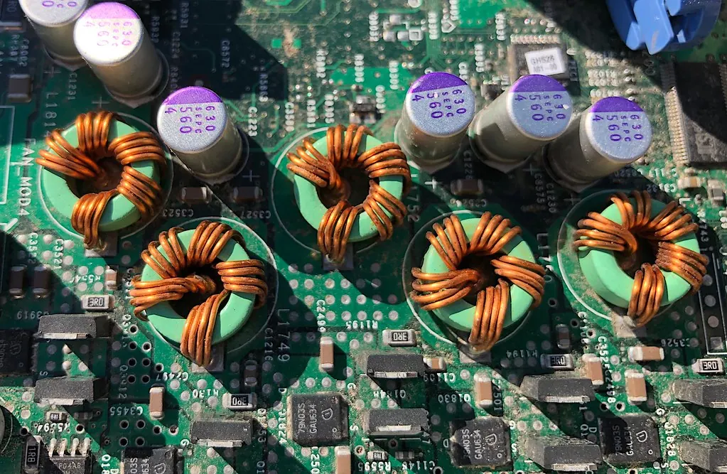
FFast
Full power in milliseconds
CCycles
Hundreds of thousands to millions
PPower
High power, seconds to minutes
- Duration range
- ms–minutes
- Round-trip efficiency
- 90–98 %
- Cycle life
- 500,000+
- Service life
- 10–20 yrs
- Power range
- kW–tens of MW
Section 01
Electrical Storage — Overview
A battery stores energy in chemical bonds; electrical storage keeps it as separated electric charge (in a capacitor) or as current circulating in a coil (in SMES). Because nothing has to react or move, it can deliver or absorb full power within milliseconds and repeat that hundreds of thousands of times.
The price of that speed is energy content: a supercapacitor holds only a few per cent of the energy of a lithium-ion battery of the same weight. Electrical storage is therefore a specialist for seconds-to-minutes duties — power quality, ride-through, smoothing, braking energy and grid stability — and is often paired with a battery that carries the hours.
1.1Electrical storage against a lithium-ion battery
| Property | Supercapacitor (EDLC) | Lithium-ion capacitor | SMES | Lithium-ion battery |
|---|---|---|---|---|
| How energy is held | Charge at a carbon surface | Carbon surface + lithium in graphite | Magnetic field of a superconducting coil | Lithium in electrode crystals |
| Response | Milliseconds | Milliseconds | Milliseconds | Tens–hundreds of ms |
| Typical duration | Seconds to about a minute | Seconds to a few minutes | Seconds | 1–4 h |
| Cycle life | 500,000–1,000,000+ | 100,000–1,000,000 | Practically unlimited | 3,000–10,000 |
| Cell energy density | ≈3–10 Wh/kg | ≈10–30 Wh/kg | Very low (system level) | ≈150–250 Wh/kg |
| Cell power density | ≈5–15 kW/kg | ≈3–10 kW/kg | Very high | ≈0.3–3 kW/kg |
| Working temperature | About −40 to +65 °C | About −20 to +70 °C | Coil at 4–77 K (cryogenic) | About −20 to +55 °C |
| Maturity | Commercial | Commercial, growing | Demonstration / niche | Commercial, dominant |
1.2The members of the family
01
CommercialEDLC supercapacitors
Activated-carbon electrodes storing charge in the electric double layer. The workhorse: robust, very long life, wide temperature range.
02
Niche / R&DPseudocapacitors
Metal-oxide or polymer electrodes that add fast surface reactions to the double layer for more energy per cell.
03
CommercialHybrid supercapacitors
One capacitive electrode and one battery-type electrode, trading some cycle life for higher energy.
04
CommercialLithium-ion capacitors
A pre-lithiated graphite anode with a carbon cathode: two to four times the energy of an EDLC, still very fast.
05
DemonstrationSMES
A superconducting coil held at cryogenic temperature, storing energy as circulating current with near-zero loss.
06
CommercialAdvanced capacitors
Film, ceramic and electrolytic power capacitors, DC-link banks and pulsed-power dielectrics used inside converters and grids.
1.3Strengths and limits in plain terms
Where it shines
6- Instant response — faster than any grid event
- Huge number of cycles with little wear
- High efficiency for short bursts
- Works in heat and cold that trouble batteries
- Exact state of charge from voltage alone
- No thermal-runaway chemistry in EDLC cells
Where it falls short
6- Small energy for its size and cost
- Voltage falls as it discharges, so a converter is needed
- Self-discharge over days to weeks
- Cost per kWh far above batteries
- SMES needs cryogenic cooling and is costly
- Few makers of cells in India today
All figures on this page are indicative ranges from public literature and manufacturer data sheets; actual values differ by product, temperature and duty. They are given to explain the technology, not as a guarantee for any project.
Section 02
Working Principle of Electrical Storage
Every capacitor is two conductors separated by an insulator. Push charge onto one side and an electric field builds across the gap; the energy sits in that field until it is let out. A supercapacitor makes the gap only a few molecules thick and the surface area enormous, which is why one cell the size of a drinks can reaches thousands of farads.
SMES works on the magnetic side: current flowing in a coil builds a magnetic field. In a normal copper coil the current dies away in milliseconds through resistance; in a superconducting coil the resistance is zero, so the current — and the energy — circulates until a converter draws it out.
2.1Why supercapacitors reach thousands of farads
Capacitance of a parallel-plate capacitor
C = ε₀ · εᵣ · A / d
Capacitance rises with the surface area of the electrodes and falls with the gap between the charges. Activated carbon offers roughly 1,000–2,000 m² of surface per gram, and the double layer gap is under a nanometre, so capacitance per gram is many thousands of times that of an ordinary capacitor.
| Symbol | Meaning |
|---|---|
| ε₀ | Permittivity of free space, 8.85 × 10⁻¹² F/m |
| εᵣ | Relative permittivity of the material between the charges |
| A | Electrode surface area (m²) |
| d | Distance between the charge layers (m) |
2.2Three ways electrical storage holds energy
Double layer (EDLC)
4- Ions from the electrolyte line up against the charged carbon surface
- No electrons cross into the material — purely physical
- Fully reversible, hence very long life
- Energy limited by the voltage the electrolyte can stand
Pseudocapacitance
4- Fast, shallow reactions on the electrode surface
- Electrons do cross, but only at the surface
- More charge per gram than a double layer
- Some wear each cycle, so shorter life
Magnetic (SMES)
4- Direct current flows in a superconducting coil
- Energy stored in the magnetic field around it
- No resistance, so almost no loss while stored
- Cooling power is the main running cost
2.3One charge–discharge cycle of a supercapacitor bank
- Grid or brake energy arrives
- Converter raises bank voltage
- Ions gather at electrode surfaces
- Energy held in the electric field
- Event detected
- Converter draws current as voltage falls
- Power delivered to grid or load
2.4How fast it can respond
Time constant
τ = R · C
The internal resistance (ESR) and capacitance set how fast a cell can be charged or emptied. Large supercapacitor cells have time constants around one second, which means a full discharge in a few seconds is natural for them; a battery takes far longer because its chemistry is slower.
| Symbol | Meaning |
|---|---|
| τ | Time constant (s) |
| R | Equivalent series resistance, ESR (Ω) |
| C | Capacitance (F) |
2.5Power against energy (the Ragone picture in words)
| Device | Energy per kg | Power per kg | Natural discharge time |
|---|---|---|---|
| Film / electrolytic capacitor | Below 0.1 Wh/kg | Very high | Microseconds–milliseconds |
| EDLC supercapacitor | ≈3–10 Wh/kg | ≈5–15 kW/kg | ≈1–60 s |
| Lithium-ion capacitor | ≈10–30 Wh/kg | ≈3–10 kW/kg | ≈5 s–a few minutes |
| Lithium-ion battery | ≈150–250 Wh/kg | ≈0.3–3 kW/kg | ≈15 min–4 h |
Energy and power densities are cell-level indicative values; a complete system with racks, converters and cooling has roughly a third to a half of the cell figures.
Section 03
EDLC Supercapacitors (Ultracapacitors)
The electric double-layer capacitor is what most people mean by a supercapacitor or ultracapacitor. Two activated-carbon electrodes coated on aluminium foil are separated by a thin porous film and soaked in electrolyte. When charged, ions pack against each carbon surface, forming two charge layers in series.
EDLCs are mature and made in very large numbers for vehicles, wind-turbine pitch systems, rail and grid support. Their life is set mainly by voltage and temperature, not by the number of cycles.
3.1What is inside a cell
Electrodes
4- Activated carbon, often made from coconut shell
- Surface area ≈1,000–2,000 m²/g
- Coated on etched aluminium foil current collectors
- Advanced options: carbide-derived carbon, graphene, carbon nanotubes
Electrolyte and separator
4- Organic: salt in acetonitrile or propylene carbonate, ≈2.5–3.0 V per cell
- Aqueous: about 1 V per cell, safe and cheap but low energy
- Ionic liquids: up to ≈3.5 V, still mostly in development
- Separator: thin paper or polymer film
Packaging
4- Cylindrical cans (large cells ≈1,000–3,400 F)
- Prismatic and pouch cells
- Laser-welded or bolted terminals
- Safety vent for gas pressure
Modules
4- Cells in series with balancing circuits
- Common modules ≈16 V, 48 V, 56 V and 125 V
- Temperature and voltage monitoring
- Busbars, insulation, cooling fins or fans
3.2Typical large EDLC cell (indicative)
| Parameter | Typical value |
|---|---|
| Rated voltage | 2.7–3.0 V |
| Capacitance | ≈1,000–3,400 F |
| Equivalent series resistance (ESR) | ≈0.15–0.5 mΩ |
| Stored energy (3,000 F at 2.7 V) | ≈3 Wh per cell |
| Mass | ≈0.5 kg |
| Peak current | Up to ≈1,000–2,000 A for short pulses |
| Cycle life | 500,000–1,000,000+ to end of life |
| Calendar life | ≈10–15 years at moderate voltage and temperature |
| Self-discharge | Voltage falls noticeably over days to weeks |
3.3What wears an EDLC out
- High voltage: holding cells at full rated voltage speeds up ageing; a small voltage derating extends life markedly
- High temperature: as a rule of thumb, life roughly halves for each ≈10 °C rise
- Unequal cells: without balancing, the weakest cell in a string is over-charged
- End of life is usually defined as capacitance down ≈20–30 % or ESR doubled
- Cycling itself causes little wear compared with batteries
- Wear shows as gradual fade, not sudden failure, so it can be tracked
3.4Energy of one cell
Cell energy
E = ½ · C · V²
½ × 3,000 F × (2.7 V)² ≈ 10,900 J ≈ 3.0 Wh
A large 3,000 F cell at 2.7 V holds about 3 watt-hours — enough to run a 100 W lamp for under two minutes — but can deliver it in a second or two. Banks therefore use hundreds to thousands of cells.
| Symbol | Meaning |
|---|---|
| C | Cell capacitance (F) |
| V | Cell voltage (V) |
Cell values are representative of large commercial EDLCs from public data sheets; each product line differs.
Section 04
Pseudocapacitors, Hybrid Supercapacitors and Lithium-ion Capacitors
To get more energy from a capacitor, designers either add fast surface reactions (pseudocapacitance) or replace one electrode with a battery-type electrode (hybrid). The most successful hybrid is the lithium-ion capacitor (LIC), which has the carbon cathode of a supercapacitor and the graphite anode of a lithium-ion battery.
These cells sit between supercapacitors and batteries: more energy and lower self-discharge than an EDLC, but a narrower voltage window and, usually, fewer cycles.
4.1The three routes
01
Pseudocapacitors
Electrodes of ruthenium oxide, manganese oxide or conducting polymers such as polyaniline store charge through fast surface reactions. Higher capacitance per gram, but cost (ruthenium) or cycle life limits their use mainly to small devices and research.
02
Asymmetric hybrids
A carbon electrode paired with a battery-type electrode such as nickel hydroxide or lead dioxide (the idea behind lead-carbon designs). More energy, moderate cycle life, often aqueous and low-cost.
03
Lithium-ion capacitors
Graphite anode pre-loaded with lithium plus an activated-carbon cathode in a lithium-salt electrolyte. Works between about 2.2 and 3.8 V, holds 10–30 Wh/kg, and keeps very fast response and long life.
4.2EDLC, hybrid and LIC compared (indicative)
| Property | EDLC | Asymmetric hybrid | Lithium-ion capacitor |
|---|---|---|---|
| Cell voltage window | 0–2.7/3.0 V | Depends on chemistry | ≈2.2–3.8 V (must not go lower) |
| Energy density | ≈3–10 Wh/kg | ≈10–20 Wh/kg | ≈10–30 Wh/kg |
| Cycle life | 500,000–1,000,000+ | ≈50,000–500,000 | ≈100,000–1,000,000 |
| Self-discharge | Moderate–high | Moderate | Low (close to a battery) |
| Can rest at 0 V | Yes (safe for transport) | Varies | No — the anode is damaged |
| Typical duty | 1–30 s bursts | 10 s–a few minutes | 5 s–a few minutes |
4.3Lithium-ion capacitor in more detail
Why it is useful
4- Two to four times the energy of an EDLC of the same size
- Low self-discharge — holds charge for weeks
- Fast response and high power like a supercapacitor
- Narrower voltage swing, so the converter is simpler
What to watch
4- Must stay above its minimum voltage (about 2.2 V)
- Contains lithium — battery-style transport and fire rules apply
- Charging at very low temperature needs care
- Fewer suppliers and less field history than EDLCs
4.4Where these cells are chosen
- Duties of tens of seconds to a few minutes, too long for an EDLC bank of sensible size
- Uninterruptible supplies that must bridge until a generator starts
- Renewable ramp-rate control at plant level
- Rail and crane energy recovery with higher energy per stop
- Backup power where batteries would be cycled too often
- Space-limited sites where EDLC energy density is too low
Ranges are indicative; hybrid and lithium-ion capacitor products vary widely and their performance should be checked against the maker's tested data.
Section 05
Superconducting Magnetic Energy Storage (SMES)
SMES stores energy in the magnetic field of a coil wound from superconducting wire and cooled below its critical temperature. Once charged, direct current circulates with almost no loss; a power converter can then draw full power from it in milliseconds.
The coil itself is extremely efficient, but the refrigeration that keeps it cold runs all the time, and superconducting wire is costly. SMES has therefore stayed in specialist roles: stabilising transmission lines, protecting critical industrial loads, pulsed power and research.
5.1Main parts of an SMES unit
- Superconducting coil (solenoid or toroid)
- Cryostat — an insulated, vacuum-jacketed vessel
- Cryogenic refrigerator (cryocooler) or liquid helium / nitrogen supply
- Current leads from room temperature to the coil
- Power conditioning system (AC/DC converter and DC chopper)
- Quench detection and protection (dump resistor)
- Magnetic shielding and exclusion zone
- Controls, monitoring and grid interface
5.2Low- and high-temperature superconductors
| Item | Low-temperature (LTS) | High-temperature (HTS) |
|---|---|---|
| Typical wire | Niobium–titanium (NbTi), Nb₃Sn | REBCO / YBCO tape, Bi-2212 / Bi-2223 |
| Operating temperature | ≈4.2 K (liquid helium) | ≈20–77 K (cryocoolers or liquid nitrogen) |
| Cooling burden | High | Lower, simpler |
| Wire cost | Lower | Higher, but falling |
| Maturity | Long history in magnets (MRI, accelerators) | Growing; several demonstrators |
5.3Energy in a coil
Magnetic energy
E = ½ · L · I²
½ × 10 H × (1,000 A)² = 5 MJ ≈ 1.4 kWh
Energy grows with the square of the coil current. A 10-henry coil carrying 1,000 A stores about 5 megajoules — enough to deliver 5 MW for one second. This shows why SMES suits short, powerful duties rather than bulk energy.
| Symbol | Meaning |
|---|---|
| L | Coil inductance (H) |
| I | Coil current (A) |
5.4Uses, history and limits
Where SMES has been used
5- Damping power oscillations on long transmission lines — the Bonneville Power Administration in the USA tested a 30 MJ unit from 1983
- Ride-through for sensitive industrial plants (small "micro-SMES" units)
- Voltage support on weak networks
- Pulsed power for research and defence
- Grid demonstrations in Japan, Korea, China and Europe
Why it is rare
5- Cost of superconducting wire and cryostat
- Refrigeration load runs day and night
- Strong magnetic fields need exclusion zones
- Quench (sudden loss of superconductivity) must be managed safely
- Supercapacitors and batteries now cover many of the same duties more cheaply
SMES is at demonstration stage for grid use. BARREL can support feasibility studies and technology partnerships for SMES; commercial deployments in India would follow pilot results.
Section 06
Advanced and Power Capacitors
Beyond supercapacitors, ordinary power capacitors do essential storage work inside every inverter, drive and substation — but over microseconds to milliseconds, not seconds. They smooth DC links, filter harmonics, supply reactive power and fire pulsed loads.
Research is also pushing new materials — graphene electrodes, solid electrolytes and high-energy dielectrics — that may close part of the gap between capacitors and batteries.
6.1Types of power capacitor
| Type | What it is | Typical use |
|---|---|---|
| Polypropylene film | Metallised plastic film, self-healing | DC-link in inverters, AC filters, power factor correction |
| Aluminium electrolytic | Oxide layer on etched foil, liquid electrolyte | DC buses in drives and power supplies |
| Ceramic (MLCC) | Stacked ceramic layers | Snubbers, gate drives, high-frequency filtering |
| Shunt capacitor banks | Many film units in racks at 11–400 kV | Reactive power and voltage support at substations |
| Series capacitors | Capacitors inserted in a transmission line | Raising line transfer capacity |
| Pulse discharge capacitors | High-voltage, low-inductance designs | Pulsed power, research, medical and test equipment |
A power-factor or shunt capacitor bank stores very little energy — it exchanges reactive power fifty times a second. It improves voltage and losses but does not shift energy in time, so it is not a substitute for supercapacitors or batteries.
6.3Materials on the horizon
01
Graphene and nanotubes
Electrodes with more accessible surface and higher conductivity, aiming at more energy and power per cell.
02
Solid and gel electrolytes
Removing flammable liquid solvents and allowing thin, flexible or structural cells.
03
Ionic-liquid electrolytes
Wider voltage windows (up to ≈3.5 V or more), since energy rises with the square of voltage.
04
High-energy dielectrics
Polymer and ceramic films with higher breakdown strength for compact pulse and DC-link capacitors.
05
Structural supercapacitors
Load-bearing body panels that also store charge, studied for vehicles and aircraft.
06
Biomass carbons
Activated carbon from agricultural residues such as coconut shell — a field where India already has raw-material strength.
6.4Supercapacitors inside grid equipment
- STATCOM with supercapacitor on its DC link adds short real-power support to its reactive power
- Wind-turbine pitch systems use supercapacitors to feather the blades in a fault
- Grid-forming inverters can use a supercapacitor buffer to supply synthetic inertia
- Dynamic voltage restorers inject stored energy to correct voltage sags
Section 07
Where Electrical Storage Fits
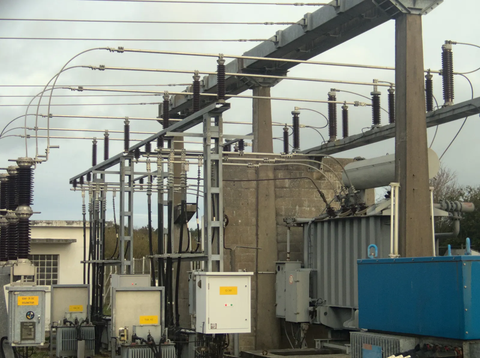
Electrical storage earns its place wherever power must arrive instantly, cycle constantly, or both. The test is simple: if the need is measured in seconds and repeats many times a day, electrical storage is usually the right tool; if it is measured in hours, a battery is.
7.1Main applications
01
Grid frequency & inertia
Fast frequency response and synthetic inertia at substations and renewable parks, acting before slower reserves arrive.
02
Voltage support
Real and reactive power injection to hold voltage during faults and switching events on weak networks.
03
Renewable smoothing
Evening out second-to-minute swings of solar under passing clouds and of wind gusts at the point of connection.
04
Industrial power quality
Ride-through of voltage dips and short interruptions for semiconductor, pharma, textile and process plants.
05
Rail and metro
Capturing braking energy at traction substations or on board and returning it when trains accelerate.
06
Ports, cranes and lifts
Peak lifting power and energy recovery when loads are lowered, reducing diesel or grid peaks.
07
Data centres and UPS
Bridging seconds until generators start, with no battery room and a very long service life.
08
Heavy industry pulses
Arc furnaces, welders, presses and test benches with sharp power peaks that disturb the supply.
09
Hybrid with BESS
Supercapacitors take fast peaks so batteries cycle gently and last longer.
7.2Typical duty by application (indicative)
| Application | Power | Duration per event | Events | Usual choice |
|---|---|---|---|---|
| Voltage-dip ride-through | 100 kW–10 MW | 0.1–3 s | Tens per year | EDLC |
| Grid fast frequency response | 1–50 MW | 1–30 s | Many per day | EDLC / LIC / hybrid with BESS |
| Solar or wind smoothing | 1–20 MW | 10 s–a few minutes | Hundreds per day | LIC or hybrid with BESS |
| Metro wayside recovery | 1–3 MW | 10–30 s | Every train stop | EDLC |
| Crane energy recovery | 100 kW–1 MW | 10–60 s | Each lift | EDLC / LIC |
| Generator bridge (UPS) | 100 kW–5 MW | 5–30 s | Rare | EDLC / LIC |
| Line oscillation damping | 10–100 MW | Seconds | On events | SMES / supercap STATCOM |
7.3Rail in a little more detail
- A braking train turns its motion back into electricity; if no other train is drawing power nearby, that energy is burnt in resistors
- A wayside supercapacitor bank at a DC traction substation (750 V or 1,500 V DC) soaks up the braking energy and returns it seconds later
- It also props up line voltage at the end of long sections, so trains accelerate better
- On-board units let light-rail vehicles run short stretches without overhead wire; some Chinese trams recharge at stops in seconds
- Energy savings reported in public studies are typically around 10–30 % of traction energy, depending on traffic
Powers, durations and savings are indicative ranges from public studies; every site needs its own measured duty profile.
Section 08
Pairing Electrical Storage with Batteries
A battery is good at hours and poor at thousands of tiny, fast cycles; a supercapacitor is the opposite. In a hybrid system the controller sends the fast, small fluctuations to the supercapacitor and the slow, large energy flows to the battery, so each does what it is best at.
The result is a smaller or longer-lived battery, a quicker response to grid events and, in many duties, a lower lifetime cost.
8.1Power split
- Grid or load signal
- Hybrid EMS
- Filter splits fast and slow parts
- Fast part → supercapacitor
- Slow part → battery
- Converters combine output
- Grid
8.2The simplest split rule
Low-pass filter sharing
P_bat = smoothed(P_total, τ) · P_sc = P_total − P_bat
The controller passes a smoothed (averaged) version of the demanded power to the battery and lets the supercapacitor supply the difference. A longer smoothing time τ protects the battery more but needs a bigger supercapacitor bank. The bank's charge is gently returned to the middle of its range between events.
| Symbol | Meaning |
|---|---|
| P_total | Power the grid or load asks for (kW) |
| P_bat | Battery share (kW) |
| P_sc | Supercapacitor share (kW) |
| τ | Filter time constant (s), typically a few seconds to a few minutes |
8.3Ways to connect the two
| Configuration | How it works | Good for | Watch for |
|---|---|---|---|
| Passive parallel | Battery and supercapacitor tied directly on one DC bus | Small, simple systems | Little control; supercap only helps with very fast peaks |
| Semi-active | One storage on a DC/DC converter, the other on the bus | Vehicles, cranes, UPS | Converter sized for the controlled side |
| Fully active DC-coupled | Each storage on its own DC/DC converter to a shared inverter | Grid and renewable plants | Two converters, more cost, full control |
| AC-coupled | Separate inverters for battery and supercapacitor on the AC side | Adding a supercap to an existing BESS | Two grid connections to coordinate |
8.4Control strategies
Common
4- Low-pass filter split
- Rate-limit on battery power
- Rule-based (supercap first, battery after a threshold)
- State-of-charge recovery for the supercap
Advanced
4- Model-predictive control using forecasts
- Optimisation for battery degradation cost
- Frequency-domain sharing for grid services
- AI-tuned parameters from operating data
8.5Benefits
- Longer battery life through fewer micro-cycles and lower peak currents
- Higher peak power from a smaller battery
- Faster response for grid codes and frequency services
- Less battery heating, so lighter cooling
- Lower lifetime cost of storage in high-cycling duties
- Better performance in very hot or cold weather
The gain from hybridising depends heavily on the duty profile; BARREL recommends a simulation on measured data before deciding.
Section 09
Technical Architecture and Components
A grid-scale supercapacitor system is built up in layers: cells into modules, modules into strings, strings into racks or containers, then a converter, transformer and switchgear connect it to the grid. Each layer adds monitoring and protection.
9.1From cell to grid
- Cell (2.7 V)
- Module (16–125 V)
- String (400–1,200 V DC)
- Rack / container
- DC/DC + inverter (PCS)
- Transformer
- Switchgear
- Grid or load
9.2Main components
Storage section
6- Cells and modules
- Cell balancing boards
- Module and rack monitoring
- Busbars and DC cabling
- DC fuses and disconnectors
- Pre-charge and discharge circuits
Power section
6- Bidirectional DC/DC converter
- Grid inverter (PCS)
- Filters (LCL, EMI)
- Step-up transformer
- LV/MV switchgear and breakers
- Auxiliary power supply
Control and support
6- Energy management system (EMS)
- SCADA and plant controller
- HVAC or forced-air cooling
- Fire detection and suppression
- Earthing and lightning protection
- Enclosure or building
9.3Cell balancing options
| Method | How it works | Pros | Cons |
|---|---|---|---|
| Passive (resistor) | Bleeds charge from high cells through resistors | Cheap, simple | Wastes energy, adds self-discharge |
| Active (switched) | Moves charge from high cells to low cells | Efficient, tighter balance | More electronics, higher cost |
| Zener / shunt regulator | Clamps each cell at a set voltage | Fast protection | Heat at full voltage |
9.4SMES architecture differs
- Coil in a cryostat replaces the cell racks
- A DC chopper controls coil current; an inverter links to the grid
- Cryocooler and vacuum pumps are critical auxiliaries
- Quench detection and an energy dump resistor protect the coil
Voltage levels shown are typical; each manufacturer's module and string designs differ.
Section 10
Power Conversion, EMS and SCADA
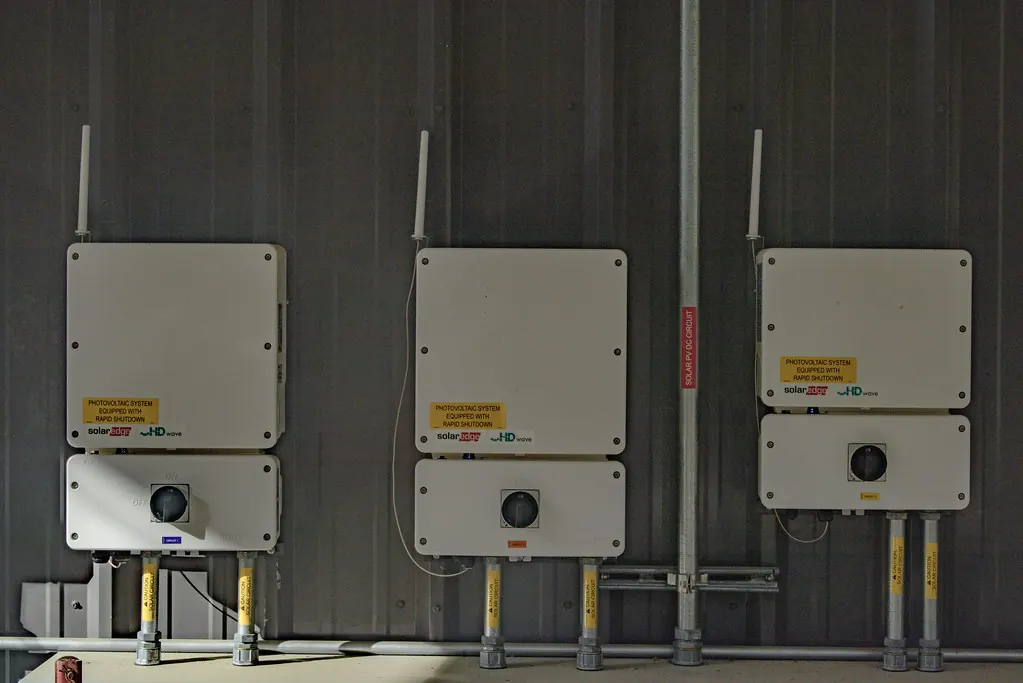
A supercapacitor's voltage falls steadily as it gives up energy — from full to half voltage as three-quarters of the energy is used. A power converter turns that falling DC voltage into steady grid AC or a fixed DC bus, and does it fast enough to keep up with the storage.
Above the converter, the energy management system decides when to charge and discharge, and SCADA links the plant to the grid operator.
10.1Converter types
DC side
4- Bidirectional buck-boost DC/DC converter
- Interleaved multi-phase DC/DC for high current
- Dual active bridge (isolated) where galvanic isolation is needed
- Direct connection to a traction DC bus via chopper
AC side
4- Two-level or three-level grid inverter (PCS)
- Grid-following control for most duties
- Grid-forming control for synthetic inertia and weak grids
- Modular multilevel converter for large or HV systems
10.2Control functions
01
Fast frequency response
Injects or absorbs power in proportion to frequency deviation within tens of milliseconds.
02
Synthetic inertia
Responds to the rate of change of frequency, mimicking the spinning mass of a generator.
03
Voltage support
Supplies reactive and real power to hold voltage during dips and faults.
04
Ramp-rate control
Limits how fast a solar or wind plant's output may change, as grid rules require.
05
Ride-through
Detects a dip and carries the load until the supply returns or a generator starts.
06
Peak and pulse shaving
Supplies short load peaks from storage so the grid sees a smooth demand.
10.3Control hierarchy
- 1Cell level: balancing and voltage/temperature limits (module electronics)
- 2Converter level: current and voltage control in microseconds to milliseconds
- 3Plant level: EMS decides power set-points, state-of-charge and mode
- 4Site level: plant controller coordinates with solar, wind, BESS and loads
- 5Grid level: SCADA links to the load despatch centre for set-points and data
10.4Common communication protocols
- IEC 61850
- IEC 60870-5-104
- DNP3
- Modbus TCP
- CAN / CANopen
- OPC UA
- IEEE C37.118 (PMU data)
Grid-forming and fast-frequency functions must be set to the connecting utility's requirements; BARREL coordinates settings with the transmission or distribution licensee.
Section 11
Grid and Site Integration
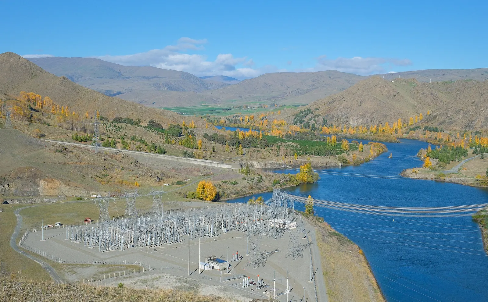
Electrical storage can connect at almost any point: inside a factory's low-voltage switchboard, on an 11 or 33 kV feeder, at a 66–220 kV substation, beside a solar or wind park, or on a metro's DC traction supply. Each point has its own rules, studies and protection.
11.1Connection points
| Connection | Typical voltage | Typical size | Who approves |
|---|---|---|---|
| Factory or building | 415 V AC | 100 kW–2 MW | Site owner, electrical inspector |
| Distribution feeder | 11–33 kV | 1–20 MW | DISCOM, state electrical inspectorate |
| Transmission substation | 66–400 kV | 10–100 MW | STU or CTU, CEA connectivity rules |
| Renewable park | 33 kV collection / 220–400 kV export | Few MW to tens of MW | Plant owner, grid operator for the whole plant |
| Metro / rail traction | 750 V or 1,500 V DC; 25 kV AC | 1–3 MW per substation | Metro or railway authority |
11.2Studies usually needed
- Power-quality measurement of the existing site or feeder
- Load flow and short-circuit studies
- Electromagnetic transient (EMT) simulation for fast events
- Harmonic and resonance study
- Protection coordination and relay settings
- Grid-code compliance (fault ride-through, frequency response)
- Earthing and insulation coordination
- Control interaction with nearby inverters and FACTS devices
11.3Connecting in India — typical path
- 1Confirm the use case and connection point with the owner
- 2Apply to the DISCOM, STU or CTU as applicable for connectivity
- 3Carry out and submit the required system studies
- 4Design to CEA technical standards for connectivity and safety regulations
- 5Get electrical inspectorate approval before charging
- 6Commission with the licensee and grid operator witnessing tests
- 7Register for any ancillary service or scheduling as required
Approval routes differ by state and by connection level; the steps above are a general outline, not legal advice.
Section 12
Sizing and Design Calculations
Sizing electrical storage starts from the power and the seconds needed, not from MWh. Then the voltage window, number of cells, converter rating and margins for ageing and temperature follow. The worked example below sizes a bank for 1 MW held for 10 seconds.
12.1Step 1 — energy needed
Energy from power and time
E = P · t / η
1,000 kW × 10 s = 10,000 kJ = 10 MJ ≈ 2.8 kWh (before losses)
Multiply the power by the seconds it must be held. Divide by the discharge efficiency of bank and converter (often 0.9–0.95) to find what the bank must give up.
| Symbol | Meaning |
|---|---|
| P | Power to deliver (kW) |
| t | Duration (s) |
| η | Discharge efficiency (fraction) |
12.2Step 2 — usable share of the energy
Depth of discharge from voltage
Share used = 1 − (V₂ / V₁)²
Discharge to half voltage: 1 − 0.5² = 0.75 → 75 % of the stored energy
Because energy goes with the square of voltage, a bank discharged to half voltage has already given up three-quarters of its energy. Going lower gains little and forces the converter to handle very high currents.
| Symbol | Meaning |
|---|---|
| V₁ | Maximum (fully charged) bank voltage (V) |
| V₂ | Lowest working voltage (V) |
12.3Step 3 — bank capacitance
Capacitance needed
C = 2 · E / (V₁² − V₂²)
2 × 10,000,000 J / (800² − 400²) = 20,000,000 / 480,000 ≈ 42 F
With a bank swinging between 800 V and 400 V, about 42 farads of bank capacitance delivers 10 MJ. Add 20–30 % for end-of-life capacitance fade and losses — about 50–55 F.
| Symbol | Meaning |
|---|---|
| E | Energy to deliver (J) |
| V₁, V₂ | Maximum and minimum bank voltage (V) |
12.4Step 4 — cells in series and parallel
Cell count
Nₛ = V₁ / V_cell · C_string = C_cell / Nₛ · Nₚ = C_bank / C_string
800 V / 2.7 V ≈ 300 cells; 3,000 F / 300 = 10 F per string; 52 F / 10 F ≈ 5–6 strings → about 1,500–1,800 cells
Series cells set the voltage; capacitance divides by the number in series, so parallel strings add it back. The example bank of about 1,800 cells of 3,000 F stores roughly 5.5 kWh in total and uses about 4 kWh of it — a comfortable margin over the 2.8 kWh needed.
| Symbol | Meaning |
|---|---|
| Nₛ | Cells in series per string |
| Nₚ | Parallel strings |
| C_cell | Capacitance of one cell (F) |
12.5Step 5 — converter current and losses
Peak current at minimum voltage
I_max = P / V₂ · Loss = I² · R_ESR
1,000,000 W / 400 V = 2,500 A at the end of discharge
Current is highest when bank voltage is lowest, so the DC/DC converter, fuses and busbars are sized at V₂. Resistive loss in the bank (I² × ESR) sets the heat the cooling system must remove.
| Symbol | Meaning |
|---|---|
| I_max | Peak DC current (A) |
| R_ESR | Total series resistance of the bank (Ω) |
12.6Live estimator
Enter the power in kW, how many seconds it must be held, the bank's maximum voltage and the lowest working voltage as a percentage of maximum. The estimator returns the energy in kWh, the bank capacitance in farads from E = ½·C·(V₁² − V₂²), and the share of the stored energy that this voltage window lets you use. It does not add margins: allow roughly 20–30 % extra for ageing, temperature and converter losses.
Estimate
- Energy to deliver
- 2.78 kWh
- Bank capacitance needed
- 41.7 F
- Share of stored energy used
- 75 %
- Total stored at full voltage
- 3.70 kWh
E = ½ · C · (V₁² − V₂²). Real banks add margin for ageing (capacitance fade), temperature and converter efficiency. Preliminary screening only; BARREL confirms any figure with a site study.
12.7Design rules of thumb
| Item | Typical choice | Why |
|---|---|---|
| Minimum voltage | ≈50 % of maximum | Uses 75 % of energy, keeps converter current reasonable |
| Cell voltage derating | ≈0.1–0.2 V below rating | Extends calendar life markedly |
| End-of-life margin | 20–30 % extra capacitance | Capacitance fades with age |
| Ambient design temperature | Site maximum + enclosure rise | Life roughly halves per ≈10 °C |
| Converter rating | Peak power at V₂ | Current is highest at low voltage |
| Standby state of charge | Mid-range for two-way services | Ready to absorb or deliver |
The worked example uses representative figures for teaching; a real design uses the chosen cell's data sheet, measured duty cycles and a thermal and lifetime model.
Section 13
Engineering Deliverables Register
A well-run project produces a known set of documents, each checked and approved at the right stage. The register below is a typical list for a grid-connected supercapacitor or hybrid system; smaller industrial projects need a shorter set.
13.1Typical deliverables
| No. | Deliverable | Stage | Purpose |
|---|---|---|---|
| D-01 | Power-quality measurement report | Feasibility | Records the real dips, swings and duty profile |
| D-02 | Duty-cycle and use-case definition | Feasibility | Sets power, duration and number of events |
| D-03 | Technology selection report | Feasibility | Compares EDLC, LIC, SMES, battery and hybrid |
| D-04 | Sizing and lifetime calculation | Basic design | Cells, voltage window, margins, life |
| D-05 | Single-line diagram | Basic design | Shows connection, protection and metering |
| D-06 | System studies (load flow, short circuit, EMT, harmonics) | Basic design | Proves grid compatibility |
| D-07 | Control philosophy and EMS functional specification | Basic design | Defines modes, set-points and interfaces |
| D-08 | Equipment specifications and data sheets | Detailed design | For tendering and purchase |
| D-09 | Layout, civil and foundation drawings | Detailed design | Containers, trenches, fire separation |
| D-10 | Cable schedule and earthing design | Detailed design | Sizing, routing and safety |
| D-11 | Protection settings and coordination | Detailed design | Relay and fuse settings |
| D-12 | HVAC and thermal design | Detailed design | Keeps cells in their temperature window |
| D-13 | Fire and safety risk assessment | Detailed design | Hazards, controls, emergency plan |
| D-14 | SCADA I/O list and communication design | Detailed design | Signals to the operator and grid |
| D-15 | FAT and SAT procedures | Manufacturing / site | Agreed tests and pass criteria |
| D-16 | Commissioning report and as-built drawings | Handover | Record of the finished plant |
| D-17 | O&M manual and spares list | Handover | How to run and maintain the system |
13.2Good practice
- One numbered register kept live from day one
- Revision control with dates and approvers
- Owner's engineer review at each stage gate
- Vendor documents checked against the specification
The register is a typical example; the actual list is agreed with the owner and lender at the start of each project.
Section 14
Site Selection, Feasibility, Civil and Mechanical Works
Electrical storage is compact compared with energy stored, but it must sit close to the load or connection it serves, stay cool, and be safely separated from people and other equipment. Feasibility checks that a site can offer all three.
14.1Site selection factors
Electrical
4- Distance to the connection point
- Fault level and grid strength
- Space in switchgear for a new bay
- Earthing conditions
Physical
4- Footprint for containers or rooms
- Ground bearing capacity and flood level
- Access for cranes and trucks
- Ambient temperature and dust
Regulatory and safety
4- Clearances from buildings and boundaries
- Fire-brigade access
- Land use and local permissions
- Magnetic exclusion zone for SMES
14.2Feasibility study steps
- 1Collect load and power-quality data (often 2–4 weeks of logging)
- 2Define the duty and the value of solving it
- 3Screen technologies and sizes
- 4Check site space, access and connection
- 5Estimate capital and running costs
- 6Assess risks and approvals
- 7Recommend a configuration and next steps
14.3Civil and mechanical scope
| Item | Typical scope |
|---|---|
| Foundations | RCC plinths or pile caps for containers, transformer and PCS skids |
| Enclosures | ISO-style containers or a prefabricated building with insulated walls |
| Cable routes | Trenches, trays, ducts and sealed wall entries |
| Cooling | Air-conditioning or forced-air units sized for cell and converter losses |
| Fire separation | Spacing or fire-rated walls between containers and transformers |
| Drainage and oil containment | Bunds for oil-filled transformers, site drainage |
| Fencing and security | Perimeter fence, gates, lighting and CCTV |
| SMES extras | Cryostat foundation, vibration isolation, cryogen storage and ventilation |
Supercapacitor banks typically occupy far less area than an equal-power battery, but more area than an equal-power inverter alone; space needs should be checked with the selected supplier's layouts.
Section 15
Turnkey EPC Delivery
Electrical storage projects are usually shorter than battery or pumped-storage projects — months rather than years — but they combine power electronics, grid work and controls, so interfaces must be managed tightly.
15.1Project phases
- 1Concept and feasibility (measurement, duty, technology choice)
- 2Basic design and grid applications
- 3Tendering and supplier selection
- 4Detailed design and approvals
- 5Manufacturing and factory acceptance tests
- 6Civil works and delivery to site
- 7Installation, cabling and integration
- 8Site acceptance tests and grid compliance tests
- 9Commercial operation and handover to O&M
15.2Work packages
| Package | Contents |
|---|---|
| Storage | Cells, modules, racks, balancing, monitoring, enclosures |
| Power conversion | DC/DC converters, inverters, filters, controls |
| Electrical BoP | Transformer, switchgear, cables, earthing, protection, metering |
| Controls | EMS, plant controller, SCADA, communication, cyber security |
| Civil and mechanical | Foundations, buildings, HVAC, fire systems, fencing |
| Testing and commissioning | FAT, SAT, grid tests, performance tests |
15.3Delivery models
01
Full EPC
One contractor takes design, supply, construction and performance responsibility.
02
EPCM
The owner buys equipment; an engineer manages design and construction for a fee.
03
Supply + supervision
Equipment supplied with specialist supervision; the owner's team installs.
04
Storage as a service
A provider owns and runs the system and charges for the service delivered.
15.4Interface risks to manage
- Converter and cell supplier compatibility (voltage window, current limits)
- EMS commands versus converter response times
- Protection settings across storage, converter and grid
- Grid-code tests that need the utility's presence
- Lead times for imported cells and cryogenic equipment
- Warranty boundaries between suppliers
Industrial supercapacitor projects can often be delivered in about 4–9 months from order; grid-scale and SMES projects take longer. Durations are indicative.
Section 16
Equipment, Supply Chain and Manufacturing in India
Large supercapacitor cells are made mainly in China, the USA, South Korea, Japan and Europe. India has strong makers of converters, transformers, switchgear, cables and power capacitors, and a large supply of coconut-shell activated carbon — the raw material for supercapacitor electrodes — but little cell manufacturing today.
16.1Equipment and Indian sourcing (indicative)
| Equipment | Indian sourcing today | Comment |
|---|---|---|
| Supercapacitor cells (large) | Mostly imported | Small Indian production and start-ups emerging |
| Lithium-ion capacitor cells | Imported | Few global makers |
| Modules and racks | Partly assembled in India | Assembly is a natural first step for local value |
| DC/DC converters and inverters | Made in India | Many domestic power-electronics makers |
| Transformers and switchgear | Made in India | Mature domestic industry |
| Cables and busbars | Made in India | Mature domestic industry |
| Power film capacitors | Made in India | Established domestic makers |
| Activated carbon | Made in India | Electrode-grade purity needs further processing |
| Superconducting wire and cryocoolers | Imported | Specialist global supply |
16.2Value chain
- Raw carbon (coconut shell)
- Electrode-grade activated carbon
- Electrode coating on foil
- Cell winding and filling
- Module assembly
- System integration
- Installation and O&M
16.3Policy and procurement points
India
4- Make in India and public procurement local-content preference
- BIS standards and quality-control orders where they apply
- Customs duty on imported cells and modules
- Approved lists for government and PSU tenders
Supply risks
4- Concentration of cell supply in a few countries
- Shipping time and freight cost
- Currency movement on imported content
- Long-term spares availability
16.4How BARREL approaches supply
- Selects cells and converters through OEM partners on tested data
- Prefers Indian converters, transformers and balance of plant
- Plans module assembly in India where volumes allow
- Secures spares and warranty back-to-back with suppliers
Sourcing status is a general picture from public information and changes quickly; it is checked for each project.
Section 17
Testing and Commissioning
Testing proves three things: that every cell and module meets its data sheet, that the converter and controls respond as specified, and that the whole plant meets the grid's or the site's requirements.
17.1Test sequence
- 1Incoming inspection of cells and modules
- 2Factory acceptance test (FAT) of modules, racks and converters
- 3Mechanical completion and visual checks on site
- 4Insulation resistance and earthing tests
- 5Protection and interlock tests
- 6Energisation and pre-charge
- 7Functional tests of EMS modes
- 8Performance tests (power, duration, efficiency, response time)
- 9Grid-code compliance tests with the licensee
- 10Trial run and handover
17.2Key tests
| Test | What it checks |
|---|---|
| Capacitance | Stored-charge capability against rating |
| ESR (internal resistance) | Losses and power capability |
| Leakage current / self-discharge | Cell quality and balancing losses |
| Cell voltage balance | Balancing circuits keep cells within limits |
| Insulation and high-voltage withstand | Safety of the DC system to earth |
| Thermal run at rated duty | Cooling keeps cells within temperature limits |
| Step response | Time from command to full power (milliseconds) |
| Round-trip efficiency | Energy out divided by energy in at rated duty |
| Fault ride-through and frequency response | Grid-code behaviour |
| Harmonics and power quality | Emission limits at the connection point |
17.3Extra tests for SMES
- Vacuum and leak tests on the cryostat
- Controlled cool-down and temperature stability
- Current ramp tests to rated current
- Quench detection and energy dump tests
Test methods follow the applicable IEC standards and the agreed specification; pass criteria are set in the FAT and SAT procedures.
Section 18
Operations, Maintenance, Monitoring and Digital Tools
Supercapacitor systems need little routine maintenance — no electrolyte top-ups, no reconditioning — but they need watching. Capacitance slowly fades and resistance slowly rises; good monitoring shows when, and digital tools forecast it.
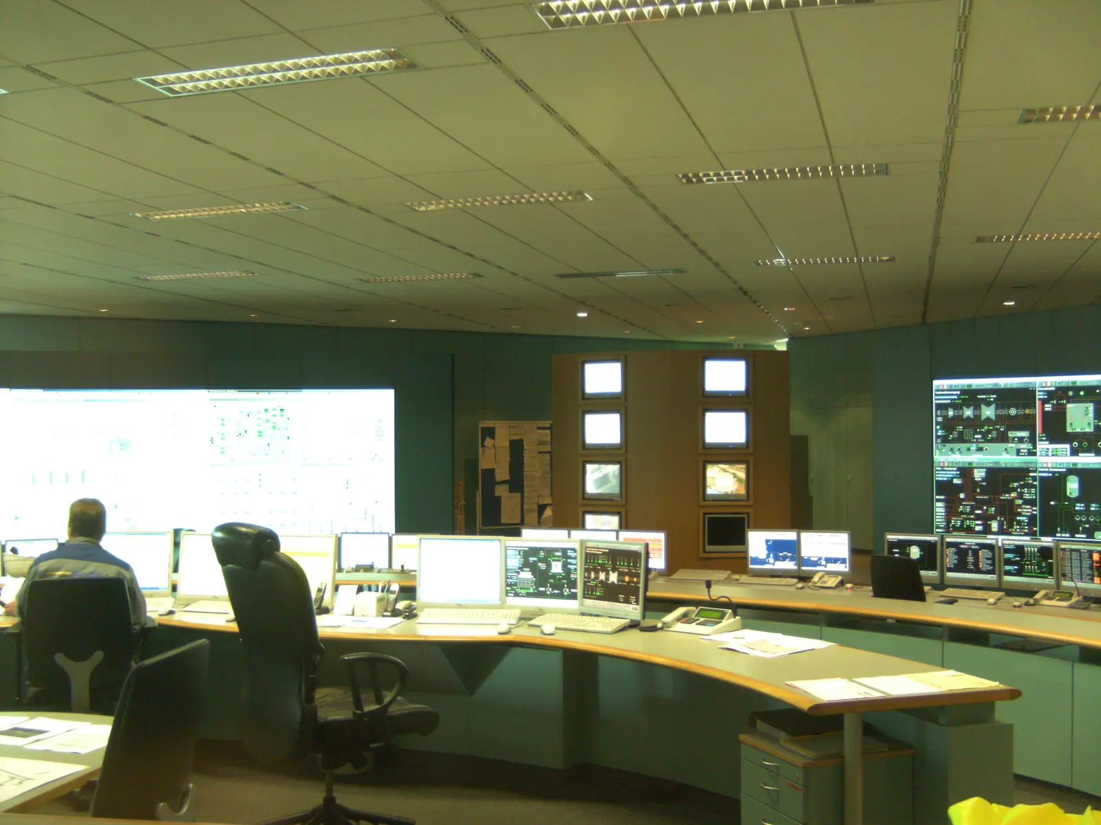
18.1Typical maintenance schedule
| Frequency | Task |
|---|---|
| Continuous | Remote monitoring of voltages, temperatures, alarms and availability |
| Monthly | Review of performance data and alarm history |
| Quarterly | Air filters, fans and HVAC checks; visual inspection |
| Yearly | Thermal imaging of connections, torque checks, capacitance and ESR estimate, protection test |
| Every 3–5 years | Converter overhaul items (fans, filter capacitors) as per maker |
| SMES | Cryocooler service intervals, vacuum checks, helium or nitrogen supply |
18.2What to track
Health indicators
4- Capacitance against new value
- ESR against new value
- Spread of cell voltages
- Cell and enclosure temperatures
Service indicators
4- Availability (%)
- Response time to commands
- Energy throughput and cycles
- Events served and missed
18.3Digital and AI tools
01
Remote monitoring
Secure dashboards with alarms, trends and reports for owner and O&M team.
02
Digital twin
A model of the bank and converter that predicts temperature, ageing and remaining life.
03
Predictive maintenance
Analytics spot rising ESR or hot spots before they cause a trip.
04
AI-tuned control
Learning from duty data to tune filter times and set-points in hybrid systems.
18.4End-of-life signs
- Capacitance below ≈70–80 % of rated value
- ESR about double its new value
- Cells failing to hold balance
- Required duty no longer met with margin
Schedules are typical; the supplier's O&M manual and warranty terms govern each system.
Section 19
Safety, Risk, Environment and Circularity
EDLC cells cannot go into the self-heating thermal runaway that lithium-ion batteries can, but a charged bank still holds dangerous energy at high voltage, and organic electrolytes are flammable. SMES adds strong magnetic fields and cryogenic hazards.
On the environmental side, supercapacitors use mostly common materials — carbon, aluminium, polymer and a salt solution — and their long life means fewer replacements than batteries.
19.1Hazards and controls
| Hazard | Where | Controls |
|---|---|---|
| Electric shock and arc flash | Charged banks, DC busbars | Discharge before work, interlocks, insulated tools, arc-rated PPE, lock-out |
| Stored charge after shutdown | Any capacitor | Discharge resistors, shorting links, verify zero voltage |
| Flammable electrolyte | Organic-electrolyte cells | Vents, fire detection, separation, suitable suppression |
| Toxic fumes in fire | Acetonitrile-based cells, plastics | Fire-brigade plan, ventilation, exclusion zones |
| Over-voltage and over-temperature | Cells and modules | Balancing, voltage limits, temperature trips |
| Lithium hazards | Lithium-ion capacitors | Battery-style fire and transport rules |
| Strong magnetic field | SMES | Exclusion zone, signage, no ferrous tools, implant warnings |
| Cryogens (asphyxiation, cold burns) | SMES | Oxygen monitors, ventilation, cryogenic PPE |
| Quench | SMES | Detection, dump resistor, pressure relief |
19.2Safe work on a supercapacitor bank
- 1Isolate the converter and open DC disconnectors
- 2Apply lock-out and tag-out
- 3Discharge the bank through the designed discharge circuit
- 4Verify zero voltage at every section
- 5Fit shorting links before touching terminals
- 6Remove links and test before re-energising
19.3Environment and circularity
01
Materials
Carbon, aluminium foil, polymer separator and electrolyte; no cobalt or nickel in EDLC cells.
02
Long life
Ten to twenty years and very high cycling reduce replacements and waste.
03
Recycling
Aluminium and steel cases are recoverable; electrolyte must be handled as hazardous waste.
04
Transport
EDLCs ship under UN 3499 and can be shipped discharged; LICs follow lithium rules.
05
Efficiency
Low losses mean less wasted energy over life, especially in high-cycling duties.
06
E-waste rules
End-of-life electronics are handled through authorised recyclers under India's E-Waste Rules.
A project-specific hazard study and fire-risk assessment is always needed; this table is a general guide.
Section 20
Standards and Compliance
Electrical storage draws on capacitor standards, power-electronics standards, energy-storage system standards and grid codes. In India, CEA regulations and the grid code apply to connection and safety, and BIS adopts many IEC standards.
20.1International standards (typical)
| Standard | Subject |
|---|---|
| IEC 62391-1 / -2 | Fixed electric double-layer capacitors for electronic equipment |
| IEC 62576 | EDLCs for hybrid electric vehicles — test methods |
| IEC 61881-3 | Railway applications — EDLCs for power electronics |
| IEC 62813 | Lithium-ion capacitors — test methods |
| IEC 61071 | Capacitors for power electronics |
| IEC 60831 / IEC 60871 | Shunt power capacitors (low and high voltage) |
| IEC 62933 series | Electrical energy storage systems — terms, performance, safety, environment |
| IEC 62477-1 | Safety of power electronic converter systems |
| IEC 61000 series | Electromagnetic compatibility and power quality |
| IEC 61850 | Substation communication |
| UL 810A | Electrochemical capacitors (safety) |
| IEEE 1547 / IEEE 2800 | Interconnection of distributed and inverter-based resources |
| UN 3499 / UN 3508 | Transport of double-layer and asymmetric capacitors |
20.2India (typical)
| Rule or body | Applies to |
|---|---|
| CEA (Technical Standards for Connectivity to the Grid) Regulations | Connection requirements for storage and generators |
| CEA (Measures relating to Safety and Electric Supply) Regulations | Electrical safety, clearances, inspection |
| CERC Indian Electricity Grid Code (IEGC) 2023 | Grid operation, scheduling, frequency response |
| CERC Ancillary Services Regulations | Reserve services storage may offer |
| State grid codes and DISCOM rules | Distribution-level connections |
| BIS (IS adoptions of IEC standards) | Capacitors, switchgear, cables, transformers |
| RDSO specifications | Equipment for Indian Railways |
| PESO | Cryogenic and pressure vessels (SMES cryogen storage) |
| E-Waste (Management) Rules | End-of-life electronics |
20.3Certifications usually asked for
- Type-test reports
- IEC conformity
- UL listing (where specified)
- ISO 9001 factory
- ISO 14001
- ISO 45001
- Grid compliance certificate
Standard editions and Indian regulations are amended from time to time; the current versions are confirmed at the start of each project.
Section 21
Commercial Models, Costs, Revenue and Investment Risk
Electrical storage is expensive per kWh but cheap per kW and per cycle. It pays where the value lies in power, speed and cycling — avoided downtime, recovered braking energy, grid services, a longer-lived battery — not in shifting bulk energy.
21.1Indicative cost ranges
| Item | Indicative range | Comment |
|---|---|---|
| Supercapacitor storage (energy part) | ≈₹4–15 lakh per kWh | High per kWh, but systems hold few kWh |
| Power conversion and BoP (power part) | ≈₹15,000–40,000 per kW | Converter, transformer, switchgear |
| Complete seconds-duration system | ≈₹25,000–80,000 per kW | Depends heavily on duration and size |
| Lithium-ion capacitor storage | Higher per kW than EDLC, lower per kWh | Suits longer durations |
| SMES | Project-specific, well above supercapacitors | Demonstration costs |
| Annual O&M | ≈1–2 % of capex | Monitoring, HVAC, inspections |
21.2Why cost per cycle matters
Storage cost per kWh cycled
Cost per cycle = Capex per kWh / (Cycle life × Depth used)
₹8,00,000 / (1,000,000 × 0.75) ≈ ₹1.1 per kWh cycled
Spread over a million cycles, even a very expensive kWh of supercapacitor becomes cheap to cycle. A battery at a much lower capex per kWh but a few thousand cycles can cost more per kWh cycled in a duty with many shallow cycles.
| Symbol | Meaning |
|---|---|
| Capex per kWh | Storage cost per kWh of energy (₹) |
| Cycle life | Number of cycles to end of life |
| Depth used | Share of stored energy used each cycle |
21.3Where the value comes from
01
Avoided downtime
One voltage dip can scrap a batch in a fab or a pharma line; ride-through value is often the biggest.
02
Energy recovery
Recovered braking or lowering energy cuts electricity bills in metros, ports and lifts.
03
Demand charges
Shaving short peaks can reduce contract demand and penalties.
04
Grid services
Frequency and reserve services where markets or contracts reward fast response.
05
Grid-code compliance
Ramp-rate and ride-through compliance for renewable plants without oversizing a battery.
06
Battery life extension
In a hybrid, fewer battery replacements over the project life.
21.4Investment risks and mitigations
| Risk | Mitigation |
|---|---|
| Revenue stream not yet priced in India (fast frequency) | Base the case on site savings; treat grid revenue as upside |
| Faster-than-expected ageing | Voltage derating, thermal design, performance warranty |
| Technology change | Modular design, open interfaces, standard converters |
| Import cost and currency | Indian balance of plant, price-variation clauses |
| Supplier exit | Spares holding, second-source options, escrow of control software |
| Wrong sizing | Measured duty data and simulation before purchase |
21.5Commercial models
Owner-financed
3- Capex purchase with EPC contract
- O&M contract with availability guarantee
- Payback from savings
Third-party
3- Storage as a service (monthly fee)
- Shared-savings contract
- Lease or BOOT for utilities and metros
All costs are broad indicative ranges converted from public international data and vary with exchange rates, scale, duration and supplier; they are not BARREL quotations.
Section 22
India and Global Markets and Policy
Worldwide, supercapacitors are a mature product in vehicles, wind turbines, rail, cranes and electronics, and are growing in grid and renewable support. India's market is smaller but its drivers are strong: a fast-growing share of solar and wind, metro expansion in many cities, sensitive manufacturing such as semiconductors, and grid rules that increasingly ask for fast response.
22.1India — drivers
Grid and renewables
4- Large solar and wind additions towards national non-fossil targets
- Falling system inertia as inverter-based generation grows
- FDRE and round-the-clock tenders that combine storage with renewables
- Grid code and ancillary-service regulations that reward reserves
Industry and transport
4- Metro rail networks in many cities
- Semiconductor and electronics manufacturing push
- Ports and logistics modernisation
- Data-centre growth needing reliable power
22.2Policy instruments relevant to storage in India
| Instrument | What it does | Relevance to electrical storage |
|---|---|---|
| Viability Gap Funding (VGF) for BESS | Central support for battery storage tenders | Hybrids with supercaps can sit inside BESS projects |
| CERC Ancillary Services Regulations | Secondary and tertiary reserve markets | Fast storage can provide reserves |
| IEGC 2023 | Grid operation and frequency response rules | Sets expectations on response and ride-through |
| CEA connectivity regulations | Technical requirements for connection | Ride-through and ramp-rate rules for plants |
| Make in India / local content | Preference for domestic value | Encourages local module and system assembly |
22.3Global trends
- Fast-frequency and inertia services priced in several grids (for example in Great Britain and Australia)
- Supercapacitor-battery hybrids in renewable plants and microgrids
- Lithium-ion capacitors gaining in UPS and industrial uses
- HTS wire cost falling slowly, keeping SMES interest alive
- Continuing research on graphene and new electrolytes
- Rail operators adding wayside storage to cut traction energy
Policies and schemes change; BARREL checks the latest notifications from MNRE, CEA, CERC and state regulators for each project.
Section 23
Frequently Asked Questions and References
Short answers to the questions owners ask most, and where to read more.
23.1Frequently asked questions
What is the difference between a supercapacitor and an ultracapacitor?
None in practice — both names describe the same device, an electric double-layer capacitor with very high capacitance. Some makers prefer one name, some the other.
Can a supercapacitor replace my battery?
Only where the need is seconds to a minute or so. For hours of backup or solar shifting, a battery is far cheaper. Often the best answer is both together.
How long does a supercapacitor system last?
Typically 10–20 years and hundreds of thousands to over a million cycles, depending on voltage, temperature and duty. Life is set more by age and heat than by cycles.
How fast does it respond?
The cells respond almost instantly; the complete system with converter and controls typically reaches full power within milliseconds to tens of milliseconds.
Why does the voltage drop as it discharges?
A capacitor's voltage is proportional to its stored charge, so voltage falls steadily as energy is drawn. A DC/DC converter keeps the output steady.
Why only discharge to half voltage?
At half voltage three-quarters of the energy is already used. Going lower adds little energy but sharply raises current and converter cost.
Are supercapacitors safe?
EDLCs do not suffer thermal runaway like lithium-ion batteries, but a charged bank holds dangerous energy at high voltage and organic electrolytes can burn. Proper design, discharge procedures and fire protection are required.
Do supercapacitors lose charge when idle?
Yes, more than batteries — voltage falls noticeably over days to weeks. For grid duties the system simply tops up continuously; lithium-ion capacitors hold charge much longer.
What is a lithium-ion capacitor?
A hybrid with a battery-type graphite anode and a supercapacitor carbon cathode. It stores two to four times as much energy as an EDLC while staying fast and long-lived.
What is SMES and is it available?
Superconducting magnetic energy storage keeps energy as current in a super-cold coil. It works and has been demonstrated on grids, but cost and cooling keep it to niche and pilot uses.
Can supercapacitors help a solar plant meet grid rules?
Yes. They can control ramp rates and support fault ride-through and fast frequency response, alone or together with a battery.
How do metros use supercapacitors?
Wayside banks at DC traction substations absorb energy from braking trains and return it when trains accelerate, saving energy and supporting line voltage.
What does a hybrid supercapacitor–battery system gain?
The supercapacitor takes the fast, frequent peaks, so the battery sees fewer, gentler cycles, lasts longer and can be smaller for the same peak power.
How much space does it need?
For seconds of storage, a few megawatts usually fit in one or two containers plus converter and transformer skids; exact layouts depend on the supplier.
Is there any Indian manufacturing?
Converters, transformers, switchgear, cables, film capacitors and activated carbon are made in India. Large supercapacitor cells are mostly imported today, with local assembly growing.
What data do you need for a first estimate?
The power needed, how many seconds, how often, the connection voltage and the site conditions. A few weeks of power-quality logging gives the best basis.
Can electrical storage earn grid revenue in India?
Reserve markets exist under CERC's ancillary services rules, but a separate fast-frequency product is not yet broadly priced. Most Indian cases today rest on site savings and compliance, with grid revenue as upside.
Does BARREL manufacture supercapacitors?
No. BARREL studies, designs, supplies through OEM partners, builds and maintains systems, and is open to manufacturing partnerships in India.
23.2References
- International Energy Agency (IEA)Global energy and storage analysis
- IRENARenewables and storage reports
- NRELUS National Renewable Energy Laboratory research
- Central Electricity Authority (CEA)Indian technical standards and regulations
- Ministry of New and Renewable Energy (MNRE)Indian renewable and storage policy
- Central Electricity Regulatory Commission (CERC)Grid code and ancillary services regulations
- Bureau of Indian Standards (BIS)Indian standards
- IEC WebstoreIEC capacitor and energy-storage standards
- Supercapacitor (Wikipedia)General introduction
- Superconducting magnetic energy storage (Wikipedia)General introduction
Answers are general guidance with indicative figures; a project study is needed for firm numbers.
Section 24
BARREL Services for Electrical Storage
From a power-quality study to a supplied, commissioned and maintained system — BARREL can take one step or the whole journey, working with OEM partners for cells, converters and cryogenic equipment.
24.1What BARREL offers
01
Power-quality studies
Measuring dips, flicker and fluctuations to define the real duty and size the right system.
02
Selection & design
Supercapacitor, lithium-ion capacitor, SMES, battery or hybrid compared on cost and life for your duty.
03
Grid studies & approvals
System studies, connectivity applications and grid-code compliance support.
04
Supply
Cells, modules, converters and controls through OEM partners, with Indian balance of plant.
05
Integration & EPC
Installation at substations, plants, depots, ports and renewable parks, alone or with a BESS.
06
Testing & commissioning
FAT witnessing, site tests and grid compliance tests with the licensee.
07
O&M & monitoring
Remote monitoring, health tracking, maintenance and lifetime performance reports.
08
Finance & models
Help with capex, storage-as-a-service and shared-savings structures.
09
Partnerships
Manufacturing and technology partnerships to build supercapacitor capability in India.
24.2How an engagement starts
- 1Tell us the power, the seconds and how often
- 2We review your data or arrange power-quality logging
- 3We send a short options note with indicative sizes and costs
- 4Feasibility or detailed study if the case is good
- 5Supply, EPC and O&M proposal
BARREL works with OEM partners for equipment; scope, guarantees and timelines are set out in each proposal.
Project desk
Plan your electrical storage project with BARREL
Instant power where every millisecond counts.
Protecting a sensitive plant, steadying a renewable connection, recovering braking energy or extending a battery's life — tell us the power and the seconds you need, and we will respond with the options and next steps.
Project categories
- Supercapacitor bank
- Lithium-ion capacitor
- SMES
- Supercap + BESS hybrid
- Rail / metro energy recovery
- Industrial power quality
- Renewable ramp-rate control