
- Energy Storage
- Family 04
- Mechanical
- Long Duration
- Grid Inertia
Mechanical Energy Storage
Compressed Air | Liquid Air | Flywheel | Gravity | Pumped Heat
Energy stored in pressure, motion and height.
Mechanical systems turn electricity into pressure, motion, height or heat-and-cold and back again — from a flywheel that answers in milliseconds to compressed or liquid air that can run for many hours. They are built mostly from steel, concrete, rock and air rather than scarce battery minerals, and the main machines last for decades. BARREL can study, design, supply, build and operate mechanical storage for utilities, renewable parks and industry, working with OEM partners for the specialist machines.
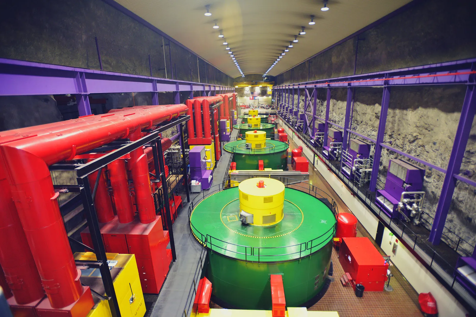
PPressure
Compressed and liquid air
MMotion
Flywheel rotors
HHeight
Gravity and lifted mass
- Duration range
- Seconds–days
- Power range
- kW–GW
- Round-trip efficiency
- 40–75 %
- Asset life
- 30–50 yrs
- Critical-mineral use
- Low
Section 01
Mechanical Storage — Overview
Mechanical energy storage keeps electricity as potential energy (a raised mass or compressed air), kinetic energy (a spinning rotor), or as the pressure and cold of liquefied air. A motor or compressor charges the store; a turbine, expander or generator discharges it back to the grid.
Pumped hydro is the largest mechanical store in the world and has its own page. This page covers the other mechanical families, which suit sites without water and height, or duties that need very fast response, very long life or real rotating inertia.
1.1The mechanical families at a glance
| Family | Stores energy as | Typical duration | Round-trip efficiency | Maturity |
|---|---|---|---|---|
| Diabatic CAES | Air pressure in a cavern; gas burnt on discharge | 4–26 h | 42–55 % (fuel counted separately) | Commercial since 1978 |
| Adiabatic CAES (A-CAES) | Air pressure plus stored heat of compression | 4–12 h | 55–70 % | First large plants (China) |
| Isothermal CAES | Air pressure, compressed at near-constant temperature | 1–8 h | Up to 70–80 % (targets) | Pilot / demonstration |
| Liquid air (LAES) | Cryogenic liquid air in insulated tanks | 4–12 h+ | 50–60 %, higher with waste heat | First commercial plants |
| Flywheel | Kinetic energy of a spinning rotor | Seconds–15 min (some 4 h) | 85–95 % (short cycles) | Commercial |
| Gravity | Height of lifted blocks or weights | 1–10 h | 75–85 % (claimed) | Demonstration to early commercial |
| Pumped thermal (PTES) | Hot and cold stores made by a heat pump | 6–12 h+ | 50–70 % (design targets) | Pilot / demonstration |
Durations, efficiencies and maturity levels are indicative ranges from public literature (IEA, IRENA, US DOE, PNNL and peer-reviewed studies). Real figures depend on design, site, duty cycle and how losses are counted.
1.2Why mechanical storage
01
Long life
Compressors, turbines, steel and concrete last 30–50 years with little or no loss of capacity over time.
02
Common materials
Mostly steel, concrete, rock and air — no lithium, cobalt or nickel, and less exposure to mineral prices.
03
Grid inertia
Large synchronous machines give real inertia, fault current and voltage support to a weak grid.
04
Cheap extra hours
Energy (MWh) grows with cavern, tank or tower size, which is often cheaper than adding more battery cells.
1.3Honest limits
- Most long-duration mechanical options are only economic at large scale (tens to hundreds of MW)
- CAES in caverns needs suitable geology, which only some regions have
- Round-trip efficiency is usually lower than lithium-ion batteries (85–90 %)
- Several technologies (isothermal CAES, gravity, PTES) still have few operating plants
- Build times are longer than battery projects — often 2–4 years
- Flywheels store little energy and are a power tool, not a bulk store
1.4Where it is used
- Renewable firming
- Peak shifting
- FDRE / RTC supply
- Frequency response
- Grid inertia
- Black start
- Transmission deferral
- Industrial heat and cold
- Data centre ride-through
- Metro braking energy
Section 02
How Mechanical Storage Works
Every mechanical store has three parts: a charging machine (motor, compressor, winch or heat pump), a store (cavern, tank, rotor, raised mass or hot and cold beds) and a discharging machine (turbine, expander, generator). In some designs one reversible machine does both jobs.
Power (MW) is set by the size of the machines; energy (MWh) is set by the size of the store. This separation lets a designer add hours cheaply — the main advantage over batteries for long duration.
2.1Four ways to hold energy mechanically
Pressure
4- Air compressed to 40–100 bar in a cavern or vessel
- Released through an expander or gas turbine
- Heat of compression lost, stored or avoided
- CAES — diabatic, adiabatic, isothermal
Cold and pressure
4- Air liquefied at about −196 °C
- Stored at near-atmospheric pressure
- Pumped, evaporated and expanded to generate
- LAES — also called cryogenic storage
Motion
4- Rotor spun by a motor-generator
- Energy rises with the square of speed
- Vacuum and magnetic bearings cut losses
- Flywheels — seconds to minutes
Height and heat
4- Heavy mass lifted by winches or cranes
- Lowered to drive generators
- Heat pump makes hot and cold stores (PTES)
- Gravity storage and Carnot batteries
2.2The common energy path
- Grid or renewable power
- Charging machine
- Store (pressure, cold, motion, height, heat)
- Discharging machine
- Generator
- Transformer
- Grid
2.3Duty against technology
| Duty | Best mechanical fit | Why |
|---|---|---|
| Frequency response, seconds | Flywheel | Millisecond response, very high cycle life |
| Power quality and UPS ride-through | Flywheel | No chemical ageing, high power density |
| Daily shifting, 4–8 h | A-CAES, LAES, gravity | Low cost per extra MWh at large scale |
| Long duration, 8–24 h | CAES in salt caverns | Cavern volume is very cheap energy |
| Brownfield mines | Gravity, underground CAES | Re-uses existing shafts and voids |
| Industry with waste heat or cold | LAES, PTES | Heat and cold integration raises efficiency |
| Coal plant repowering | PTES, A-CAES | Re-uses steam turbine, grid connection and site |
2.4Plant configurations
Stand-alone
3- Own grid connection
- Buys and sells in the market or under a storage contract
- Common for CAES and LAES
Co-located
3- Shares a substation with a solar or wind park
- Charges from on-site generation
- Supports FDRE and RTC bids
Hybrid
3- Flywheel or BESS for fast response
- CAES, LAES or gravity for hours
- One plant controller for both
Selection always starts from the duty, not the technology. BARREL compares mechanical options with batteries, pumped hydro and thermal storage on the same cost and performance basis before recommending one.
Section 03
Compressed Air Energy Storage — Diabatic CAES
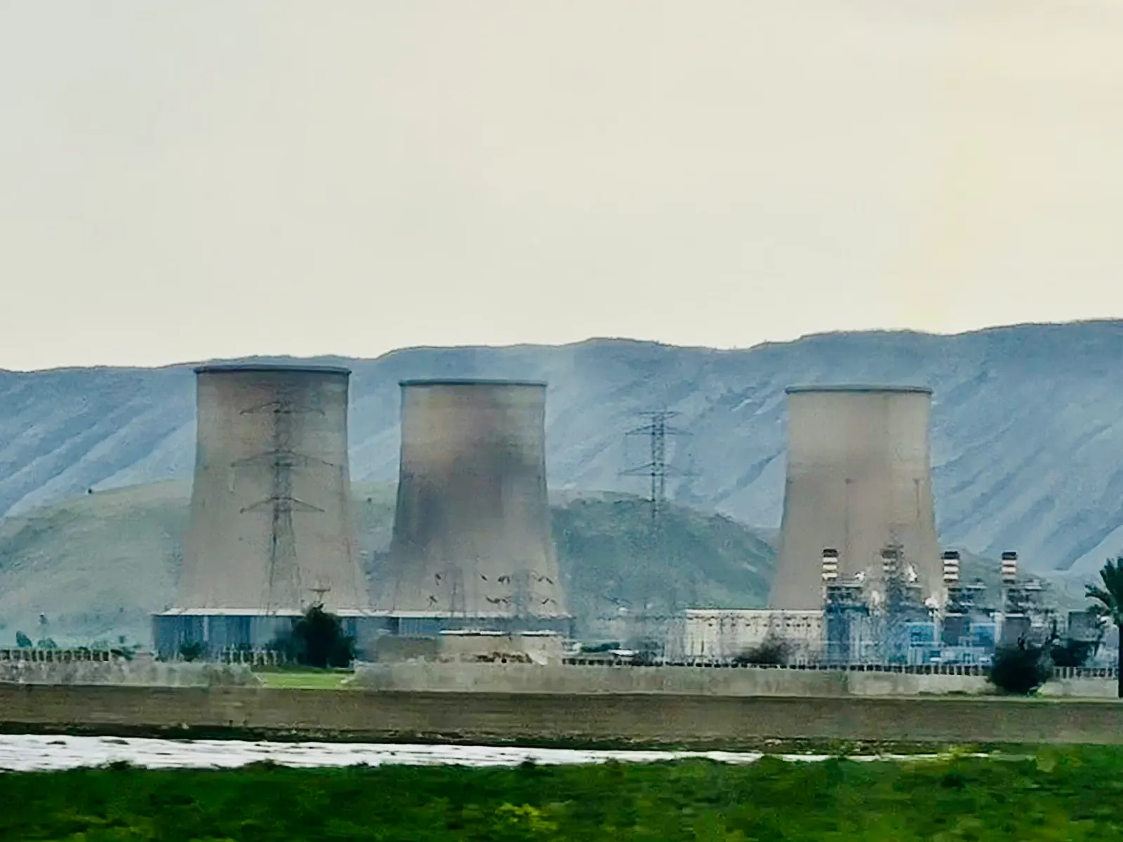
Diabatic CAES is the oldest form of CAES. Electric compressors fill an underground cavern with air during cheap or surplus hours. To generate, the air is released, heated by burning natural gas in combustors, and expanded through turbines. The heat made during compression is cooled away and lost.
Because the compressor of a normal gas turbine uses about two-thirds of its power, a CAES plant that pre-compresses the air can make two to three times more electricity from the same fuel as a simple gas turbine.
3.1Charge and discharge path
- Surplus power
- Motor-compressor train
- Intercoolers and aftercooler
- Salt cavern (about 45–75 bar)
- Recuperator and combustor
- HP and LP expanders
- Generator and grid
3.2The two long-running reference plants
| Plant | Country, year | Power | Store | Notes |
|---|---|---|---|---|
| Huntorf | Germany, 1978 | 290 MW (later about 320 MW) | Two salt caverns, about 310,000 m³ in total | World's first CAES plant; about 2–3 h at full output; efficiency about 42 % |
| McIntosh | Alabama, USA, 1991 | 110 MW | One salt cavern, about 540,000 m³ | Up to about 26 h at full output; recuperator lifts efficiency to about 54 % |
Plant figures are as widely reported in public literature and rounded. Efficiency for diabatic CAES is a mixed figure because both electricity and gas go in; different studies count it differently.
3.3Key features
01
Proven
More than four decades of operation at Huntorf and three at McIntosh show the cavern and machinery concept is sound.
02
Fuel needed
Burns gas on discharge, so it is not zero-carbon unless the fuel is biomethane or hydrogen.
03
Fast start
Units can reach full power in about 10–15 minutes and give spinning reserve and black start.
3.4Where the air can be stored
- Solution-mined salt caverns — tight, self-sealing, the cheapest per MWh
- Lined hard-rock caverns and disused mines
- Depleted gas fields and aquifers (still under study for air)
- Above-ground steel pipes and pressure vessels for small and medium plants
Section 04
Adiabatic and Isothermal CAES
Adiabatic CAES (A-CAES, also called advanced CAES) keeps the heat of compression in a thermal store — hot oil, molten salt, pressurised water, ceramic or rock beds — and uses it to reheat the air on discharge. No fuel is burnt, so the plant is emission-free when charged with clean power.
Isothermal CAES tries to avoid the heat problem altogether by compressing and expanding slowly with constant cooling and heating, often using water sprays or liquid pistons. It promises high efficiency but is still at pilot scale.
4.1CAES variants compared
Diabatic
4- Heat of compression rejected
- Gas-fired reheat
- Efficiency about 42–55 %
- Proven since 1978
Adiabatic (A-CAES)
4- Heat stored at 200–600 °C
- No fuel on discharge
- Efficiency about 55–70 %
- Large plants built in China since 2021–22
Isothermal (I-CAES)
4- Near-constant temperature
- Liquid-piston or spray cooling
- Efficiency target 70–80 %
- Mostly small vessel-based pilots
4.2A-CAES with a thermal store
- Compressor stage
- Heat exchanger to hot store
- Cavern, vessel or water-compensated cavern
- Air back through hot store
- Expander stage
- Generator
4.3Design choices
01
High-temperature store
Few compression stages; air leaves at 500–600 °C into a packed bed. Simple, but needs high-temperature pressure equipment.
02
Low/medium-temperature store
Several stages with intercoolers; heat stored at 150–350 °C in oil, salt or pressurised water. Uses more standard equipment.
03
Constant-pressure store
A water column (hydrostatic compensation) keeps cavern pressure steady, so machines run at their best point and the cavern is smaller.
4.4Where the technology stands
- China has commissioned salt-cavern A-CAES plants of about 60 MW / 300 MWh (Jintan, Jiangsu, 2022) and larger 100–300 MW units since
- Several 100 MW-class projects are under development in Australia, Canada and Europe
- Isothermal and liquid-piston systems have been tested at kW to low-MW scale
- Underwater compressed air in flexible bags has been trialled at small scale
Project sizes and dates are as reported publicly and rounded; check the latest status before relying on them. Efficiency figures are design or reported values, not guaranteed performance.
Section 05
Liquid Air Energy Storage (LAES)
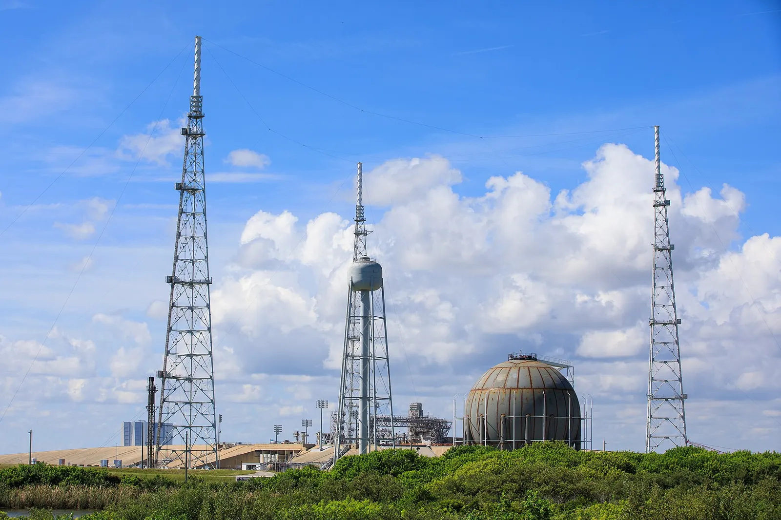
LAES cleans, compresses and cools air until it turns to liquid at about −196 °C, and keeps it in low-pressure insulated tanks. To generate, the liquid is pumped to high pressure, warmed back to a gas and expanded through turbines.
Because it needs no cavern, LAES can be built on an ordinary industrial plot. It works best where there is waste heat (to warm the air before the turbine) or waste cold (for example an LNG import terminal) to raise efficiency.
5.1The LAES cycle
- 1Air is filtered, dried and its water and CO₂ removed
- 2Compressed in several stages and cooled
- 3Cooled further in the cold box using stored cold
- 4Expanded to liquefy, then stored in insulated tanks near atmospheric pressure
- 5On discharge the liquid is pumped to 60–150 bar
- 6Evaporated, then heated with stored heat of compression or waste heat
- 7Expanded through multi-stage turbines to make power
- 8Cold released during evaporation is stored in a cold store and reused for the next charge
5.2Design points
01
Siting freedom
Tanks sit on an ordinary plot; no special geology or height is needed.
02
Energy density
Roughly 50–200 kWh per m³ of liquid air, far more than compressed air.
03
Efficiency
About 50–60 % stand-alone; higher with waste heat at 100–200 °C or waste cold.
04
Proven parts
Compressors, cold boxes, cryogenic tanks and pumps come from the industrial gas industry.
5.3Reference experience
- A 5 MW / 15 MWh demonstration plant ran near Manchester, UK, from 2018
- A 50 MW / about 300 MWh commercial plant has been under construction in the UK
- Larger plants are being planned in the UK, Spain, Australia and China
Plant sizes and efficiencies are indicative, from public reports. Liquid air is not flammable, but cryogenic liquids need proper oxygen-enrichment, cold-burn and tank-pressure safeguards.
Section 06
Flywheel Energy Storage
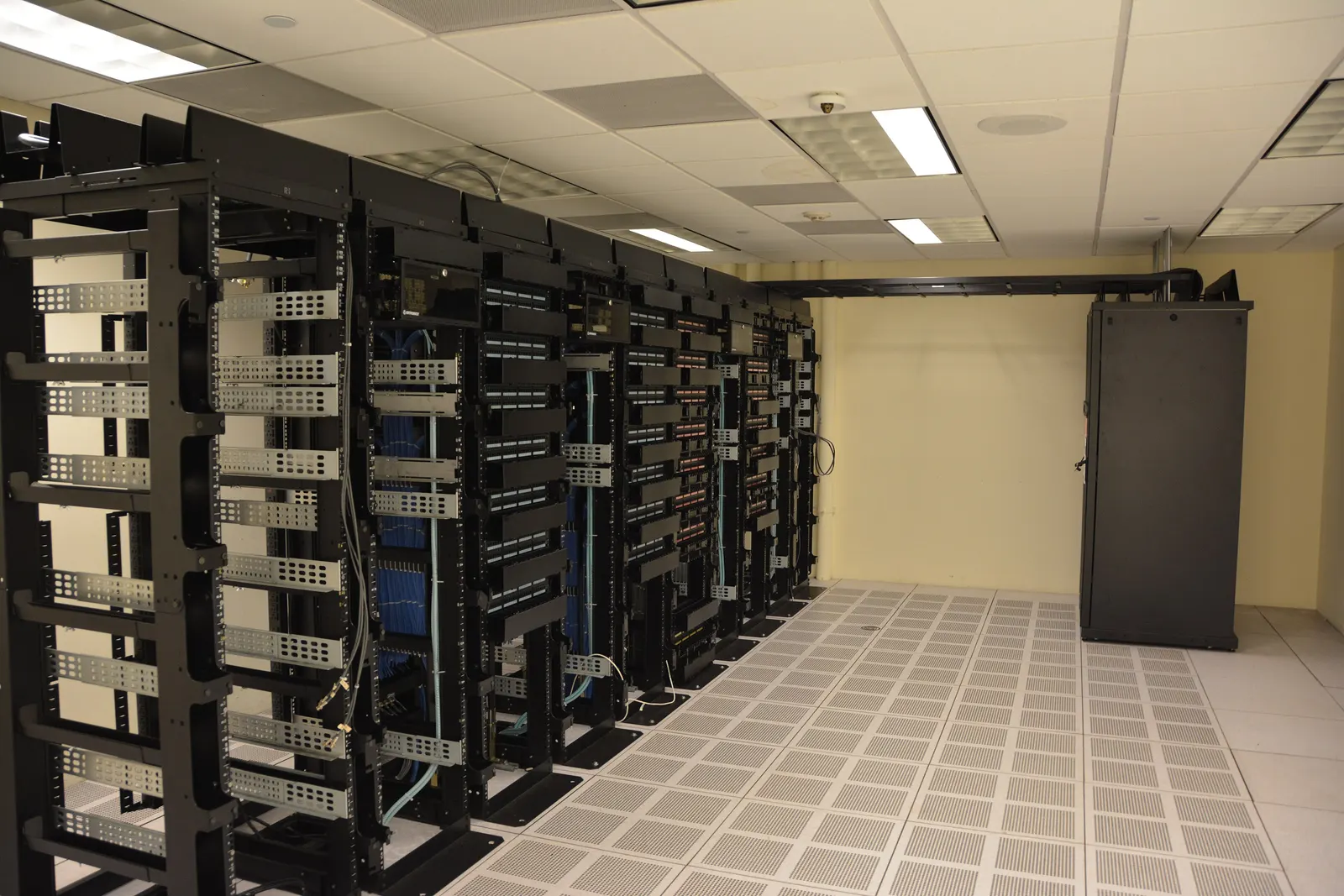
A flywheel stores energy in a heavy rotor spun up by a motor-generator. Steel rotors run at a few thousand rpm; carbon-fibre composite rotors in a vacuum on magnetic bearings run at 20,000–50,000 rpm with very low friction.
Flywheels give full power in milliseconds and can handle hundreds of thousands to millions of cycles, so they suit frequency response, power quality, UPS ride-through and braking energy recovery — not long-duration shifting.
6.1Rotor types
Low-speed steel
4- Up to about 10,000 rpm
- Heavy, robust, lower cost
- Mechanical or hybrid bearings
- UPS and industrial power quality
High-speed composite
4- 20,000–50,000 rpm
- Carbon or glass fibre rims
- Vacuum housing and magnetic bearings
- Grid frequency regulation and transport
6.2Typical characteristics
| Parameter | Typical range |
|---|---|
| Unit power | 100 kW – 2 MW per unit; plants of 20 MW+ by grouping units |
| Discharge time | Seconds to 15 minutes (a few long-duration designs reach about 4 h) |
| Response time | Under 10 ms to full power |
| Cycle life | 100,000 to over 1,000,000 cycles |
| Round-trip efficiency | 85–95 % on short cycles |
| Self-discharge | Roughly 1–5 % per hour at standby (much more for steel on mechanical bearings) |
| Design life | About 20 years, little capacity fade |
Figures are indicative ranges from manufacturer literature and public studies. Self-discharge is the main reason flywheels are not used for storage over hours.
6.3Typical uses
- Frequency regulation
- Data centre ride-through
- Hospital and semiconductor power quality
- Railway and metro braking energy
- Port cranes
- Microgrid stabilisation
- Hybrid with BESS
- Pulsed loads and test benches
6.4Reference experience
- A 20 MW flywheel frequency-regulation plant has run at Stephentown, New York, since 2011
- Flywheel UPS units are widely used in data centres and factories as a battery-free bridge to diesel start
- Rotating stabilisers (synchronous condensers with a flywheel) are used to add inertia on renewable-heavy grids
Section 07
Gravity Energy Storage
Gravity storage lifts heavy blocks or weights with electric motors and winches, then lowers them so the motors run as generators. The physics is the same as pumped hydro, but a solid mass replaces the water.
The energy stored is small per tonne, so useful plants need very large masses, great heights or both — which is why designs use tall structures, deep mine shafts, steep slopes or many thousands of blocks.
7.1Gravity concepts
Block towers and buildings
4- Cranes or lifts stack composite blocks
- Blocks often made from soil, waste or fly ash with cement
- Heights of 100–150 m
- Demonstrated in Switzerland (2020) and built at grid scale in China (2024)
Mine-shaft weights
4- Heavy weights hung in disused shafts
- Shafts of 300–1,500 m depth
- Re-uses mining sites and grid links
- Pilot rigs tested in the UK and Europe
Rail and slope
4- Heavy rail cars hauled uphill
- Regenerative braking downhill
- Needs long slopes with steady gradient
- Demonstrated in the USA
Piston and water
4- Large rock or concrete piston in a water-filled shaft
- Pumped water lifts the piston
- Combines hydro machinery with gravity
- Concept and design stage
7.2Energy in a lifted mass
Potential energy
E = m · g · h
1,000 t lifted 100 m ≈ 0.27 MWh before losses
Each tonne lifted one metre stores only about 2.7 Wh. Gravity storage therefore needs very large masses or heights for MWh-scale energy.
| Symbol | Meaning |
|---|---|
| E | Stored energy (J; divide by 3.6 × 10⁹ for MWh) |
| m | Mass lifted (kg) |
| g | 9.81 m/s² |
| h | Height lifted (m) |
7.3Strengths and watch-points
01
No fade
The mass does not age or leak; capacity stays the same for the life of the plant.
02
Fast response
Electric drives reach full power in seconds, so gravity plants can also give grid services.
03
Watch-points
Large structures, wind loads, cable and winch wear, and limited operating history; costs are still uncertain.
Gravity storage is at demonstration to early-commercial stage. Claimed efficiencies of 75–85 % and lives of 35+ years come from developers and early plants, and should be checked against independent test data.
Section 08
Pumped Thermal Energy Storage (PTES)
PTES — sometimes called a Carnot battery — uses electricity to run a heat pump that makes a hot store and a cold store at the same time. To generate, the machine runs in reverse as a heat engine between the two stores, driving a generator.
It sits between mechanical and thermal storage: the stores hold heat and cold, but the conversion is done by compressors and turbines. It can be built anywhere and can re-use parts of a retiring coal or gas plant.
8.1Main cycle types
Brayton (gas) cycle
4- Argon or air as working gas
- Packed beds of gravel or rock
- Or molten salt hot store and chilled liquid cold store
- High temperatures, high power density
Rankine / transcritical CO₂
4- Heat pump on CO₂ or refrigerant
- Hot water or salt store
- Ice or chilled store on the cold side
- Lower temperatures, standard parts
Resistive heat + steam
4- Electric heaters charge salt or rock
- Steam turbine on discharge
- Simpler, lower efficiency (30–45 %)
- Good fit for coal plant repowering
8.2How PTES charges and discharges
- Surplus power
- Heat pump (compressor + expander)
- Hot store and cold store
- Heat engine (reverse flow)
- Generator
- Grid
8.3What to know
- Round-trip efficiency targets of 50–70 % depend on very efficient compressors and expanders
- Can supply heat to industry or district heating as well as electricity
- Pilot plants have operated in Europe and the USA; first commercial projects are being planned
- Re-using a coal plant's turbine, grid link and land can cut cost and protect local jobs
PTES efficiency and cost figures are mostly from design studies and pilots; treat them as targets rather than proven fleet values.
Section 09
Technical Architecture and Components
Mechanical storage plants are built from heavy industrial equipment that is well known in power, oil-and-gas and process industries. The design skill lies in matching the machines to the store and to the duty.
9.1Main components by technology
| Technology | Charging side | Store | Discharging side | Key auxiliaries |
|---|---|---|---|---|
| Diabatic CAES | Motor, axial/centrifugal compressors, intercoolers | Salt or rock cavern, wellhead, brine string | Recuperator, combustors, HP/LP expanders, generator | Gas supply, cooling water, air drying |
| A-CAES | Compressors with heat exchangers | Cavern or vessels + hot store (oil, salt, water, rock) | Expanders with reheat from hot store | Hot-store pumps, heat-transfer fluid, insulation |
| LAES | Main air compressor, purification, cold box, liquefier | Cryogenic tanks, cold store, hot store | Cryogenic pump, evaporator, superheater, turbines | Nitrogen purge, instrument air, boil-off handling |
| Flywheel | Motor-generator, power converter | Rotor in vacuum housing | Same motor-generator | Vacuum pump, bearing controls, cooling |
| Gravity | Electric drives, winches or cranes | Blocks, weights or rail cars | Same drives as generators | Brakes, guides, structural monitoring |
| PTES | Compressor and expander (heat pump mode) | Hot and cold stores | Same or second machine set (engine mode) | Working-gas inventory, heat-transfer fluid |
9.2Plant systems
Mechanical
5- Compressor and expander trains
- Gearboxes and couplings
- Heat exchangers and coolers
- Valves, piping and wellheads
- Lifting and handling
Electrical
5- Motor-generators
- Variable-speed drives or static starters
- Step-up transformers
- MV and HV switchgear
- Auxiliary supply and DG backup
Balance of plant
5- Cooling water or air-cooled systems
- Compressed instrument air
- Fire detection and protection
- Lube oil and seal systems
- Workshops and stores
9.3Architecture decisions that drive cost
01
Separate or reversible machines
Separate compressor and expander trains allow faster switching; one reversible machine saves cost but cannot charge and discharge at once.
02
Fixed or variable speed
Variable-speed drives widen the operating range and give finer grid control, at extra cost and losses.
03
Store pressure and temperature
Higher pressure means a smaller store but thicker walls and more compression stages; the optimum is found by study.
Section 10
Power Conversion, Controls and Grid Integration
Large CAES, LAES, gravity and PTES plants usually connect through synchronous motor-generators, like a conventional power station. Flywheels and some gravity systems use power electronics. The control system ties the machines, the store and the grid together.
10.1Ways to connect to the grid
Synchronous machine
4- Direct grid connection at 11–21 kV, stepped up to 132–400 kV
- Real inertia and fault current
- Static frequency converter or pony motor for starting
- CAES, LAES, PTES
Variable-speed drive
4- Motor or generator through a converter
- Wide speed range, fast power control
- Grid-forming options
- Compressors, gravity winches
Power electronics
4- AC–DC–AC converter per unit
- Millisecond control
- Harmonic filters
- Flywheels, small gravity units
10.2Control layers
- 1Machine controls — governors, excitation, anti-surge, vibration and bearing protection
- 2Plant control system (DCS) — sequences start, charge, discharge and trips
- 3Energy management system (EMS) — schedules charging and discharging against prices and contracts
- 4SCADA and RTU — links the plant to the state or regional load despatch centre
- 5Cyber security layer — network zoning and access control as required by CEA guidelines
10.3Grid services a mechanical plant can give
| Service | Flywheel | CAES / LAES / PTES | Gravity |
|---|---|---|---|
| Primary frequency response | Yes, excellent | Yes when running | Yes |
| Secondary / tertiary reserve (SRAS, TRAS) | Short only | Yes | Yes |
| Energy shifting | No | Yes, hours | Yes, hours |
| Synchronous inertia | With synchronous design | Yes | With synchronous design |
| Reactive power and voltage support | Yes | Yes | Yes |
| Black start | Limited | Yes (with auxiliary supply) | Possible |
10.4India grid connection points
- Connectivity under the CERC connectivity and GNA regulations (ISTS) or state grid codes (intra-state)
- Compliance with CEA Technical Standards for Connectivity to the Grid, including storage provisions
- Despatch, scheduling and deviation settlement through the load despatch centres
- Metering to CEA metering regulations, with separate import and export accounting
Grid service rules and eligibility change often. Each project is checked against the current CERC, CEA and state regulator texts at the time of design.
Section 11
Civil, Geotechnical and Mechanical Works
Civil works are often the largest single cost and the longest activity on a mechanical storage project. The store — a cavern, a cryogenic tank farm, a tower or a shaft — must hold its energy safely for decades.
11.1Building the store
Salt caverns (CAES)
5- Exploration wells and core tests
- Solution mining by fresh water circulation, often 1–3 years
- Brine disposal or sale
- Sonar surveys of cavern shape
- Mechanical integrity and pressure tests
Rock caverns and mines
4- Geological and hydrogeological mapping
- Excavation by drill-and-blast or TBM
- Concrete or steel lining where rock is not tight
- Water curtain or hydrostatic compensation
Tanks and vessels
4- Flat-bottomed cryogenic tanks (LAES) on heated or ventilated foundations
- Pipe-type or spherical pressure vessels (small CAES)
- Packed-bed thermal stores in insulated concrete or steel shells
- Bunds and spill containment
Towers, shafts and frames
4- Deep pile or raft foundations
- Wind and seismic design to IS 875 and IS 1893
- Shaft lining inspection and repair (mine reuse)
- Guide rails, crane runways and structural monitoring
11.2Power house and plant civil works
- Compressor and turbine halls with heavy machine foundations (vibration-isolated)
- EOT cranes sized for the heaviest lift
- Cooling towers or air-cooled heat exchangers
- Switchyard, cable trenches and control building
- Roads, drainage, fire water and boundary works
- Laydown and storage yards for construction
11.3Mechanical erection
01
Machine trains
Alignment of compressor, gearbox, motor and expander to tight tolerances; grouting and run-out checks.
02
Piping and vessels
High-pressure and cryogenic piping, welding procedure qualification, radiography and hydro or pneumatic testing.
03
Insulation and cold work
Perlite or vacuum insulation of cold equipment, and hot insulation of thermal stores and ducts.
Salt cavern leaching times and tank sizes vary widely with geology and design; durations here are indicative.
Section 12
Sizing and Design Calculations
First-pass sizing needs only a few formulas: energy from power and hours, the physics of each store, and the efficiency chain. The figures below are worked examples for understanding, not design values. BARREL does detailed thermodynamic and dynamic modelling for every real project.
12.1Energy, duration and efficiency
Basic storage relations
E = P × t η(RT) = E(out) ÷ E(in)
100 MW × 6 h = 600 MWh delivered; at 60 % RTE about 1,000 MWh must be charged
Power is set by the machines and energy by the store. The round-trip efficiency tells you how much charging energy is needed for each MWh delivered.
| Symbol | Meaning |
|---|---|
| E | Energy delivered (MWh) |
| P | Rated discharge power (MW) |
| t | Duration at rated power (h) |
| η(RT) | Round-trip efficiency |
12.2Gravity storage — mass needed
Mass to lift
m = E ÷ (g · h · η)
10 MW × 4 h = 40 MWh, lift 150 m, η 80 % → about 122,000 t, or about 4,900 blocks of 25 t
Convert MWh to joules (× 3.6 × 10⁹), then divide by g, height and efficiency. The answer shows why gravity plants need tens of thousands of tonnes even for modest storage.
| Symbol | Meaning |
|---|---|
| m | Mass to be lifted (kg) |
| E | Energy to deliver (J) |
| g | 9.81 m/s² |
| h | Average lift height (m) |
| η | Round-trip efficiency (as a fraction) |
12.3Live estimator
Enter the discharge power (MW), duration (h), lift height (m) and round-trip efficiency (%). The estimator gives the energy delivered (MWh), the mass that must be lifted in tonnes, using m = E ÷ (g · h · η), and the number of 25-tonne blocks that mass represents. It is a first-pass physics check only — structure, drives and cost need a full design.
Estimate
- Energy delivered
- 40.0 MWh
- Mass to lift
- 1,22,324 t
- Blocks of 25 t
- 4,893
- Energy per 1,000 t lifted
- 0.33 MWh
Mass = energy ÷ (g × height × efficiency). Shows why gravity storage needs very large masses or very deep shafts. Preliminary screening only; BARREL confirms any figure with a site study.
12.4Compressed air — work in a fixed-volume store
Ideal isothermal work between two pressures
W ≈ V · [ p₁ · ln(p₁/p₀) − p₂ · ln(p₂/p₀) − (p₁ − p₂) ]
100,000 m³ cavern, 70 → 45 bar → about 2.8 kWh/m³, or about 280 MWh ideal (about 220 MWh after machine losses)
This is the most work the air could do if expanded at constant temperature from the cavern to atmosphere as the pressure falls from p₁ to p₂. Real plants differ (heat, fuel, staging), but it shows that energy grows with cavern volume and pressure swing.
| Symbol | Meaning |
|---|---|
| W | Ideal work (J) |
| V | Cavern or vessel volume (m³) |
| p₁, p₂ | Maximum and minimum store pressure (Pa) |
| p₀ | Atmospheric pressure (about 1 bar) |
12.5Flywheel — energy in a rotor
Kinetic energy of a solid disc
E = ½ · I · ω², I = ½ · m · r²
2,000 kg steel disc, radius 0.5 m, 5,000 rpm → about 9.5 kWh; about 7 kWh usable between full and half speed
Energy rises with the square of speed, so faster rotors store far more per kilogram. Usually only the energy between full and half speed is used, which is 75 % of the total. Rim speed (here about 260 m/s) is limited by rotor strength.
| Symbol | Meaning |
|---|---|
| E | Stored energy (J) |
| I | Moment of inertia (kg·m²) |
| ω | Angular speed (rad/s) = rpm × 2π ÷ 60 |
| m, r | Rotor mass (kg) and radius (m) |
12.6Liquid air — tank volume
Liquid air inventory
V = E ÷ (e · ρ) × (1 + ullage)
300 MWh at 0.15 MWh per tonne → 2,000 t; ÷ 870 kg/m³ ≈ 2,300 m³, about 2,550 m³ with 10 % ullage
e is the electricity recovered per tonne of liquid air on discharge, typically about 0.1–0.2 MWh/t depending on heat integration.
| Symbol | Meaning |
|---|---|
| V | Tank working volume (m³) |
| E | Energy to deliver (MWh) |
| e | Output per tonne of liquid air (MWh/t) |
| ρ | Liquid air density, about 870 kg/m³ |
12.7Thermal store for A-CAES or PTES
Sensible heat
Q = m · c · ΔT
100 MWh(th) in rock (c ≈ 0.85 kJ/kg·K) with ΔT = 500 K → about 850 t of rock
The hot store must hold the heat of compression (A-CAES) or the hot side of the cycle (PTES). Real designs add margin for the temperature gradient in the bed and heat losses.
| Symbol | Meaning |
|---|---|
| Q | Heat stored (J) |
| m | Store mass (kg) |
| c | Specific heat (J/kg·K) |
| ΔT | Temperature swing (K) |
All worked examples are rounded and indicative. Real designs use real-gas properties, staged compression, heat-exchanger approach temperatures, part-load curves and auxiliary loads.
Section 13
Engineering Deliverables Register
A mechanical storage project produces a large set of studies, drawings and documents. This register shows the typical deliverables by stage; the exact list is agreed for each project.
13.1Typical deliverables by stage
| Stage | Main deliverables |
|---|---|
| Pre-feasibility | Technology screening report, duty analysis, first cost and revenue estimate, site long-list |
| Feasibility / DPR | Thermodynamic cycle model, energy yield and efficiency, geology or plot study, grid study, layout, CAPEX/OPEX, financial model, risk register |
| Basic engineering (FEED) | Process flow diagrams, heat and mass balance, P&IDs, single-line diagram, equipment datasheets, plot plan, hazard studies |
| Detailed engineering | Civil and structural drawings, piping isometrics, cable schedules, protection settings, control narratives, I/O lists |
| Procurement | Technical specifications, bid evaluation, vendor document reviews, inspection and test plans |
| Construction | Method statements, quality plans, as-built drawings, welding and NDT records |
| Commissioning and handover | Commissioning procedures, performance test reports, O&M manuals, spare-parts list, training records |
13.2Specialist studies
Process
4- Cycle and pinch analysis
- Part-load and transient simulation
- Heat and cold store modelling
- Boil-off and purge study (LAES)
Electrical
5- Load flow and short circuit
- Grid code compliance (dynamic)
- Harmonics and power quality
- Protection coordination
- Insulation coordination
Safety and civil
5- HAZID and HAZOP
- Quantitative risk assessment where needed
- Cavern stability and geomechanics
- Seismic and wind design
- Rotor burst containment (flywheel)
13.3Typical tools
- Process simulators
- Thermodynamic property libraries
- Power system simulation
- Finite element analysis
- Rotor dynamics
- 3D plant design
- Geomechanical models
- Financial models
Section 14
Site Selection and Feasibility
The site decides which mechanical technologies are possible. CAES depends on geology, gravity on height or shafts, LAES and PTES on plot area and access to waste heat or cold, and all of them on a strong grid connection.
14.1What each technology needs from a site
| Technology | Key site need | Indicative footprint |
|---|---|---|
| CAES (cavern) | Salt or tight rock at about 500–1,500 m depth; brine disposal route | Small surface plant; large underground volume |
| CAES (vessels) | Flat land, safety distances | Large area per MWh |
| LAES | Industrial plot; ideally waste heat or LNG cold nearby | A few hectares for 50–100 MW |
| Flywheel | Small plot or building near the load | Very compact per MW |
| Gravity (tower) | Firm ground, low seismic and wind risk | Moderate; tall structure |
| Gravity (shaft) | Disused deep mine shaft in sound condition | Very small surface area |
| PTES | Industrial land; coal or gas plant reuse | Similar to a small thermal plant |
14.2India site notes
- Large bedded salt deposits are limited in India; rock caverns, mines or vessels are more likely for CAES
- Retiring coal units and closed mines offer land, grid links and shafts for PTES and gravity storage
- LNG terminals on the west and east coasts offer waste cold for LAES
- Solar and wind zones in Rajasthan, Gujarat, Karnataka and Tamil Nadu need firming close to the ISTS substations
- Industrial clusters with waste heat (steel, cement, refineries) suit LAES or PTES heat integration
- Seismic zone, flood risk and water availability are checked for every site
14.3Feasibility study steps
- 1Define the duty: MW, MWh, cycles per day, response time
- 2Screen sites against geology, plot, grid and access
- 3Short-list technologies for each site
- 4Run cycle models and first-pass layouts
- 5Estimate CAPEX, OPEX, efficiency and life
- 6Model revenue from tenders, markets and grid services
- 7Rank options and recommend one for the DPR
Depth ranges and footprints are indicative. Geology must be confirmed by investigation; desk data alone is not enough for a cavern decision.
Section 15
Turnkey EPC, Testing and Commissioning
BARREL can run a mechanical storage project as one programme, from pre-feasibility to commercial operation, with specialist OEM partners for the compressors, turbines, cryogenic systems, rotors and drives.
15.1Project phases
- 1Pre-feasibility and technology screening
- 2Site, geology or plot investigations
- 3Grid study and connectivity application
- 4Detailed project report and cost estimate
- 5Environment, safety and pressure-equipment approvals
- 6Tender, PPA or storage service contract
- 7Basic and detailed engineering
- 8Procurement and factory inspection
- 9Civil works and cavern, tank or tower construction
- 10Mechanical and electrical erection
- 11Testing, commissioning and performance tests
- 12Commercial operation and O&M
15.2Typical work packages
Store
4- Cavern development or mining
- Cryogenic tank farm
- Thermal stores
- Tower, shaft or rail structures
Power island
4- Compressor and expander trains
- Motor-generators and drives
- Heat exchangers
- Auxiliary systems
Electrical and BoP
4- Transformers and switchyard
- Transmission line
- DCS, EMS and SCADA
- Civil, fire, cooling and buildings
15.3Delivery models
01
Full turnkey EPC
One contract, one point of responsibility, a fixed price and a performance guarantee.
02
Multi-package EPCM
The owner signs separate packages; BARREL manages engineering, procurement and construction for them.
03
BOO / BOOT
BARREL with partners can build, own and operate the plant and sell storage services, subject to project financing.
15.4Testing and commissioning
| Stage | Main tests |
|---|---|
| Factory (FAT) | Compressor and expander performance and mechanical run tests, rotor balancing, motor and transformer routine tests, control system FAT |
| Store | Cavern mechanical integrity test, tank hydro or pneumatic test, vacuum and leak tests, thermal store heat-up |
| Pre-commissioning | Flushing, pressure tests, loop checks, protection relay tests, insulation tests |
| Cold commissioning | Rotation checks, auxiliaries on line, interlocks, trip tests |
| Hot commissioning | First charge and discharge, synchronisation, load steps, grid code compliance tests |
| Performance tests | Rated power, energy, round-trip efficiency, ramp rate, response time, auxiliary consumption |
| Trial operation | Continuous operation as set in the contract and regulator rules before COD |
Build times are indicative: about 1 year for flywheel plants, 2–3 years for LAES, gravity and PTES, and 3–5 years for cavern CAES including leaching. Pressure vessels, cryogenic tanks and caverns need specific statutory approvals (for example PESO and state inspectorates in India), confirmed site by site.
Section 16
Equipment, Supply Chain and Manufacturing in India
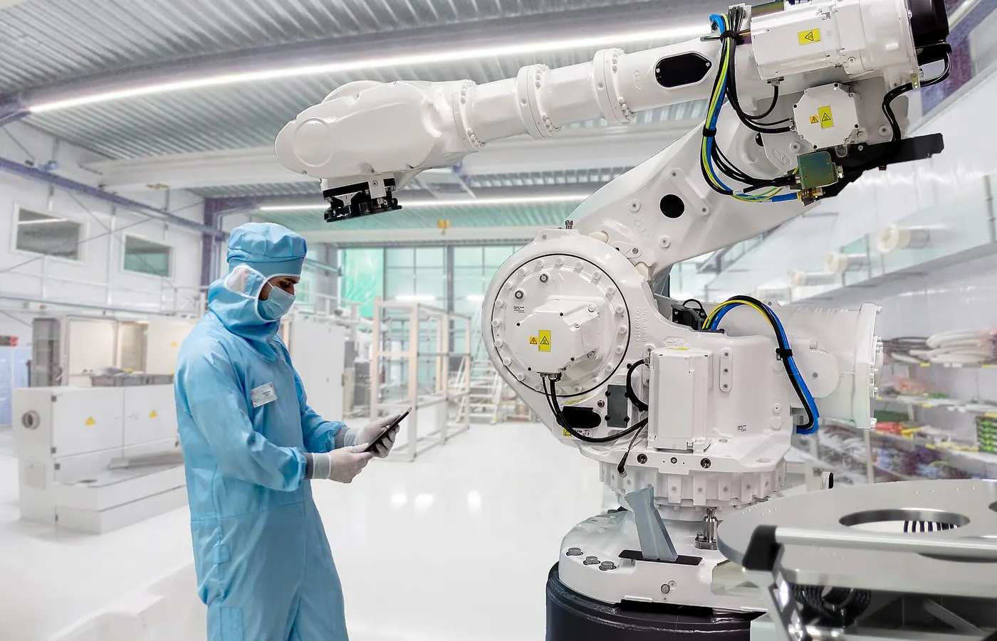
Mechanical storage relies on heavy industrial equipment that India already makes or assembles for power, steel, oil-and-gas and process plants. A large share of plant value — civil works, steel structures, vessels, heat exchangers, transformers and cables — can be sourced locally.
16.1Main equipment
Turbomachinery
5- Multi-stage compressors
- Intercoolers and aftercoolers
- Expanders and air turbines
- Motor-generators
- Gearboxes
Stores
5- Cavern wellheads and casings
- Pressure vessels and pipe stores
- Cryogenic tanks
- Packed-bed thermal stores
- Composite and steel rotors
Electrical & controls
5- Variable-speed drives
- Step-up transformers
- Switchgear
- Plant controller and SCADA
- Vacuum and bearing systems
16.2Indicative sourcing picture
| Item | India capability | Comment |
|---|---|---|
| Civil works, steel structures | Strong | Fully local |
| Pressure vessels, heat exchangers | Strong | Made to ASME and IS codes by many fabricators |
| Transformers, switchgear, cables | Strong | Local manufacture to IEC/IS standards |
| Large motors and generators | Good | Local makers for most ratings |
| Cryogenic tanks and cold boxes | Good | Industrial gas and LNG supply chain |
| Large compressors and expanders | Partial | Some local assembly; many trains imported |
| High-speed composite flywheel rotors | Limited | Mostly imported today |
| Variable-speed drives, control systems | Good | Local assembly and integration |
16.3Make in India points
- Public procurement preference rules (Make in India orders) can apply to government tenders
- Local content lowers currency risk and shortens spares supply
- Factory inspection and witness testing are planned into the schedule
- Long-lead items (compressor trains, generators, transformers) are ordered early
The sourcing picture is a general indication and changes as industry grows; each project checks current vendor capability.
Section 17
Operations, Maintenance and Digital Tools
Mechanical storage plants are maintained much like gas turbine, compressor or hydro stations: planned inspections, condition monitoring and overhauls on a running-hours basis. Digital tools help squeeze out losses and predict failures early.
17.1Typical maintenance tasks
| Interval | Typical tasks |
|---|---|
| Daily / continuous | Remote monitoring, alarms, vibration and temperature trends, store pressure and level |
| Monthly | Filters, lube oil checks, valve tests, fire system checks |
| Yearly | Minor inspections of machines, protection tests, cavern or tank inspections, vacuum system service (flywheel) |
| Every 4–8 years | Major overhaul of compressors, expanders and combustors (CAES), rotor and bearing inspection |
| Long term | Cavern sonar survey, winch and cable replacement (gravity), insulation renewal, control system upgrade |
17.2Digital and AI tools
01
Digital twin
A live model of the cycle that compares actual with expected efficiency and spots fouling, leaks or drift.
02
Predictive maintenance
Vibration, oil and temperature data analysed to plan repairs before a failure.
03
Market optimisation
Price and renewable forecasts used to plan charging and discharging for the best revenue.
17.3Key performance indicators
- Availability (%)
- Round-trip efficiency (measured)
- Auxiliary consumption
- Starts, trips and ramp performance
- Store leakage or self-discharge
- Response time for grid services
Intervals are indicative and follow OEM manuals and running hours in practice.
Section 18
Safety and Risk Management
Mechanical stores hold large amounts of energy as pressure, cold, speed or height. None of them has the thermal-runaway risk of lithium-ion batteries, but each has its own hazards that must be designed out and managed.
18.1Main hazards and controls
| Technology | Main hazards | Typical controls |
|---|---|---|
| CAES | High-pressure release, cavern instability, combustor fire (diabatic) | Pressure relief, emergency shut-down valves, cavern monitoring, gas detection |
| LAES | Cold burns, oxygen enrichment, tank over-pressure, brittle failure | Cryogenic-rated materials, relief valves, oxygen monitoring, bunding |
| Flywheel | Rotor burst, loss of vacuum, bearing failure | Containment housings, below-ground installation, overspeed trips |
| Gravity | Falling loads, cable failure, structural collapse | Redundant brakes, load monitoring, exclusion zones, structural sensors |
| PTES | Hot surfaces, high-pressure gas, hot-store fluids | Insulation, relief systems, leak detection, fire protection |
18.2Safety process
- 1HAZID at concept stage
- 2HAZOP on P&IDs during basic engineering
- 3Safety integrity level (SIL) assessment of trips
- 4Quantitative risk assessment and safety distances where needed
- 5Emergency response plan with local authorities
- 6Permit-to-work and lock-out procedures in operation
18.3Project risks
Technical
3- Geology worse than expected
- Efficiency below design
- New technology with short history
Delivery
3- Long-lead equipment delays
- Approvals taking longer
- Cost overrun on civil works
Market
3- Changing tariff and tender rules
- Falling battery prices
- Revenue uncertainty for grid services
Section 19
Standards and Compliance
There is no single code for mechanical storage. Each plant is designed to the standards of its parts — pressure equipment, turbomachinery, cryogenic tanks, electrical machines, grid connection — plus the energy storage standards that now cover all storage types.
19.1Key international standards
| Area | Standard (examples) |
|---|---|
| Energy storage systems | IEC 62933 series (electrical energy storage systems); UL 9540 (energy storage system safety) |
| Pressure vessels and piping | ASME Boiler and Pressure Vessel Code Section VIII; ASME B31.3 process piping |
| Compressors and expanders | API 617 (axial and centrifugal compressors and expander-compressors); API 618 (reciprocating compressors) |
| Cryogenic tanks | API 625 and API 620 (low-temperature storage tanks); EN 14620 (refrigerated liquefied gas tanks) |
| Salt caverns | API RP 1170 (solution-mined salt caverns for gas storage); EN 1918-3 (underground gas storage in salt caverns) |
| Rotating electrical machines | IEC 60034 series |
| Balancing and vibration | ISO 21940 (rotor balancing); ISO 20816 (vibration measurement) |
| Functional safety | IEC 61508 and IEC 61511 |
| Control and communication | IEC 61850; IEC 62443 (industrial cyber security) |
19.2India codes and rules
| Area | Rule or code (examples) |
|---|---|
| Electrical safety | CEA (Measures relating to Safety and Electric Supply) Regulations, 2023 |
| Plant construction | CEA Technical Standards for Construction of Electrical Plants and Electric Lines |
| Grid connection | CEA Technical Standards for Connectivity to the Grid; Indian Electricity Grid Code (CERC) |
| Pressure vessels and gases | PESO — Static and Mobile Pressure Vessels (Unfired) Rules, 2016; Gas Cylinders Rules where relevant |
| Unfired pressure vessels | IS 2825 |
| Structural loads and seismic | IS 875 (loads), IS 1893 (earthquake), IS 456 (concrete), IS 800 (steel) |
| Factories and workers | Factories Act and state factory rules; Occupational Safety, Health and Working Conditions Code |
| Environment | EIA Notification 2006 as applicable; state pollution control board consents |
Standards listed are examples of what usually applies; the actual list is fixed in the project's design basis, and Indian rules take precedence for projects in India. Always use the current edition.
Section 20
Environment and Circularity
Mechanical storage is built mainly from steel, concrete, rock and air, which are widely available and largely recyclable. Its environmental footprint depends on the store, the fuel (for diabatic CAES) and the source of charging power.
20.1Environmental points by technology
01
CAES
Diabatic plants emit CO₂ from gas reheat; adiabatic plants do not. Cavern leaching produces large brine volumes that must be handled responsibly.
02
LAES
Uses only air; no emissions on site. Cryogenic tanks and machines are steel and are recyclable.
03
Flywheel
Steel rotors are fully recyclable; composite rotors are harder to recycle today.
04
Gravity
Blocks can be made from local soil, mine waste or fly ash, putting waste to use.
05
PTES
Gravel, rock or salt stores; can re-use coal plant sites and reduce new land use.
06
All
Long life and no capacity fade spread the embodied carbon over 30–50 years of operation.
20.2Circularity practice
- Design for decommissioning: removable machines, recyclable steel and copper
- Re-use of brownfield land, mines, coal plants and existing grid connections
- Material passports for major equipment
- Life extension by machine overhaul rather than replacement
- Brine reuse or sale to the chemical industry where possible
20.3Environmental steps
- 1Screen the project against EIA and state rules
- 2Baseline studies: land, water, air, noise, ecology
- 3Impact assessment and management plan
- 4Consent to establish and consent to operate from the state board
- 5Monitoring and reporting during operation
Section 21
Commercial Models, Costs and Investment
Mechanical storage usually has a higher cost per MW than batteries but a lower cost for each extra hour, and a much longer life. It wins on long duration and high cycle life; batteries usually win on short duration.
21.1Indicative capital cost ranges
| Technology | Cost per kW (USD) | Cost per kWh (USD) | Notes |
|---|---|---|---|
| Diabatic CAES (salt cavern) | 1,000–1,800 | 50–150 | Cheapest per MWh for long duration where salt exists |
| Adiabatic CAES | 1,500–3,000 | 150–350 | Thermal store adds cost; no fuel |
| LAES | 1,500–3,000 | 200–500 | Falls with scale; better with waste heat |
| Flywheel | 1,000–3,000 | 2,000–10,000 | Power device; cost per kWh is high |
| Gravity | 1,500–3,500 | 200–600 | Early data; very uncertain |
| PTES | 1,500–3,000 | 150–400 | Mostly study estimates |
Cost ranges are rough, indicative figures drawn from public studies (for example PNNL, IRENA and academic reviews) and vary widely with size, duration, site and year. They are not quotes. Convert to rupees at the prevailing rate and add Indian taxes, duties and grid costs.
21.2Levelised cost of storage
LCOS
LCOS = (CAPEX × CRF + OPEX + charging cost) ÷ annual energy delivered
LCOS is the cost of each MWh delivered over the life of the plant. Long life and low fade help mechanical storage; lower efficiency raises the charging cost.
| Symbol | Meaning |
|---|---|
| CRF | Capital recovery factor = r(1+r)ⁿ ÷ ((1+r)ⁿ − 1) |
| r | Discount rate |
| n | Life in years |
| OPEX | Fixed and variable O&M per year |
21.3Revenue models in India
Contracted
3- Storage capacity contract with a utility (₹ per MW per month)
- FDRE or RTC renewable supply with storage
- Peak power supply agreements
Market
3- Energy arbitrage on power exchanges (DAM, RTM)
- Ancillary services (SRAS, TRAS) under CERC rules
- Green day-ahead market
Behind the meter
3- Demand charge reduction
- Power quality and ride-through
- Waste heat or cold integration savings
21.4Investment risks and how they are handled
| Risk | Mitigation |
|---|---|
| Technology risk (new designs) | OEM performance guarantees, independent engineer review, staged scale-up |
| Geology risk (CAES) | Early drilling and testing before final investment decision |
| Revenue risk | Long-term capacity contracts, mixed revenue stacking |
| Cost overrun | Fixed-price EPC, contingency, early ordering of long-lead items |
| Policy change | Contract change-in-law clauses, regulatory monitoring |
| Currency risk | Local content, hedging of imported equipment |
Section 22
India and Global Markets and Policy
India needs large amounts of storage to integrate its renewable targets, and policy is now technology-neutral in most tenders. Batteries and pumped hydro lead today; mechanical options are studied for long-duration and special duties.
22.1India policy framework
National policy
4- National Framework for Promoting Energy Storage Systems (Ministry of Power, 2023)
- Energy storage obligation for distribution companies and others, rising year by year
- Electricity (Amendment) Rules, 2022 recognise storage as part of the power system
- National Electricity Plan (CEA) projections of storage need
Tenders and support
4- Stand-alone storage and FDRE / RTC tenders by SECI, NTPC, NHPC, SJVN and states
- Viability gap funding currently aimed at battery storage
- ISTS charge waiver for storage, phased down for later projects
- CERC ancillary services regulations open grid services to storage
22.2Global picture
| Region | Mechanical storage activity |
|---|---|
| China | Largest builder of A-CAES; first grid-scale gravity storage; many demonstrations |
| Europe | Huntorf CAES; LAES, PTES and mine-shaft gravity pilots; long-duration storage support schemes in the UK |
| USA | McIntosh CAES; flywheel frequency regulation; DOE long-duration storage programmes |
| Australia and Canada | Large A-CAES projects in development; long-duration tenders |
| Middle East | Studies of CAES and gravity for solar firming |
22.3Outlook for India
- Long-duration storage (8 h+) need will grow as solar share rises
- Coal unit retirements open sites for PTES and A-CAES repowering
- Flywheels and rotating stabilisers can add inertia to renewable-heavy grids
- Technology-neutral tenders let mechanical options compete with batteries on delivered cost
Policy details (obligation levels, waivers, VGF eligibility) change often; this page gives the general direction. Check current Ministry of Power, MNRE, CEA and CERC notifications for exact terms.
Section 23
Frequently Asked Questions and References
Short answers to common questions, and public sources for further reading.
23.1Frequently asked questions
What is mechanical energy storage?
Storing electricity as pressure (compressed air), cold and pressure (liquid air), motion (flywheels), height (gravity) or hot and cold stores made by a heat pump (pumped thermal), then turning it back into electricity with machines.
Is pumped hydro mechanical storage?
Yes, it is the largest mechanical store. It has its own page on this site; this page covers the other mechanical options.
How long can mechanical storage discharge?
From seconds (flywheels) to many hours (CAES, LAES, gravity, PTES). McIntosh CAES can run for about 26 hours at full output.
How efficient is it?
Roughly 40–75 % round trip for the long-duration types, and 85–95 % for flywheels on short cycles. Lithium-ion batteries are usually 85–90 %.
Why choose it over batteries?
Longer life, no capacity fade, cheaper extra hours at large scale, real grid inertia and no critical minerals. Batteries are usually cheaper for short durations and small sizes.
What is the difference between diabatic and adiabatic CAES?
Diabatic CAES throws away the heat of compression and burns gas to reheat the air. Adiabatic CAES stores that heat and reuses it, so it needs no fuel.
Does CAES need a salt cavern?
Salt caverns are cheapest, but hard-rock caverns, old mines and steel vessels can also be used, at higher cost per MWh.
Is liquid air dangerous?
It is not flammable or toxic, but it is very cold and can enrich the air with oxygen if it leaks. Tanks and plant are designed with the safety rules of the industrial gas industry.
Can a flywheel store energy for hours?
Generally no. Flywheels lose energy to friction over time and are best for seconds to minutes. A few designs reach about 4 hours.
How much mass does gravity storage need?
About 2.7 Wh per tonne per metre. For 40 MWh with a 150 m lift at 80 % efficiency, about 122,000 tonnes. Use the live estimator on the Sizing tab.
What is a Carnot battery?
Another name for pumped thermal storage: a heat pump charges hot and cold stores, and a heat engine turns the difference back into power.
Can old coal plants be reused?
Yes. PTES and some thermal storage designs can re-use the steam turbine, grid connection, cooling and land of a retiring coal unit.
How long does a project take to build?
About a year for flywheels, two to three years for LAES, gravity and PTES, and three to five years for cavern CAES, after approvals.
What approvals are needed in India?
Typically grid connectivity, CEA electrical safety inspection, PESO approvals for pressure and cryogenic vessels, state pollution board consents and, where applicable, environmental clearance.
Is mechanical storage eligible for Indian storage tenders?
Many stand-alone storage and FDRE tenders are technology-neutral, so mechanical storage can bid if it meets the performance terms. Current viability gap funding is aimed at battery storage.
How long does the equipment last?
Main machines, stores and structures are designed for 30–50 years with overhauls; flywheel units typically about 20 years.
What does BARREL do in this field?
BARREL can carry out feasibility and technology selection, engineering, equipment supply through OEM partners, turnkey EPC, O&M and help with finance and tenders.
23.2References and further reading
- International Energy Agency — Energy storageGrid-scale storage tracking
- IRENA — Energy storageReports on storage technologies and costs
- US DOE — Office of Electricity, energy storageProgrammes and long-duration storage
- PNNL — Energy Storage Cost and PerformanceCost and performance database for storage types
- NREL — Energy storage researchResearch and analysis
- Central Electricity Authority (CEA), IndiaRegulations, plans and standards
- Ministry of New and Renewable Energy (MNRE)Renewable and storage policy
- Central Electricity Regulatory Commission (CERC)Grid code and ancillary services
- IEC WebstoreIEC 62933 and other standards
- Wikipedia — Compressed-air energy storageGeneral background and plant list
Links go to public organisations' pages and open in a new tab. Page addresses on outside sites may change.
Section 24
BARREL Services for Mechanical Storage
One partner from the first study to decades of operation, working with specialist OEM partners for the machines.
24.1What BARREL can do
01
Feasibility & selection
Compare CAES, LAES, flywheel, gravity and PTES with batteries and pumped hydro for your duty and site.
02
Engineering
Thermodynamic modelling, cavern, tank and vessel design, grid studies and controls engineering.
03
Equipment supply
Compressors, expanders, tanks, rotors and electricals through OEM partners.
04
Turnkey EPC
Civil, mechanical and electrical construction, testing and commissioning.
05
O&M
Operation, maintenance, performance monitoring, digital twin and life extension.
06
Finance & partnerships
Project structuring, tender support, revenue modelling and technology partnerships.
24.2How to start
- 1Tell us the power, duration and site in the enquiry form
- 2We review the duty and send first options
- 3Agree a feasibility scope and timeline
- 4Feasibility report with a recommended technology and cost
Project desk
Plan your mechanical storage project with BARREL
Pressure, motion and height — engineered for your grid.
Studying compressed or liquid air, a flywheel for grid services, gravity storage in a mine or a pumped thermal plant at a retiring coal unit — tell us the power, duration and site, and we will respond with the options and next steps.
Project categories
- Compressed air (CAES)
- Liquid air (LAES)
- Flywheel
- Gravity
- Pumped thermal
- Hybrid with BESS