
- Energy Storage
- Family 09
- Hybrid
- Round-the-Clock
- FDRE
Hybrid Energy Storage
Battery + Hydro | Battery + Thermal | Battery + Hydrogen | Supercap + BESS | Battery + Cold
Fast response from one technology, long duration from another.
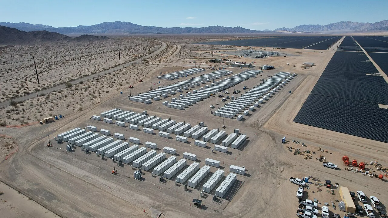
No single storage technology is best at everything. A battery answers in milliseconds but is costly for long hours; pumped hydro, thermal and hydrogen store cheaply for long hours but respond more slowly. A hybrid combines two or more of them under one energy management system so each does the part of the job it does best. BARREL designs, supplies through OEM partners, builds and operates hybrid storage for round-the-clock renewable supply, FDRE tenders, industrial microgrids and grid services.
FFast
Battery or supercapacitor for seconds to hours
LLong
Hydro, thermal or hydrogen for hours to weeks
EEMS
One controller that splits the duty
- Combined time range
- ms–weeks
- Typical firm-supply availability asked
- ≥ 80–90 %
- Lifetime cost vs one technology
- Lower
- Project range
- MW–GW
- Indian tender fit
- FDRE / RTC
Section 01
Hybrid Storage — Overview
Every storage project must cover a range of time-scales: fractions of a second for frequency, minutes for ramps, hours for the evening peak and sometimes days for cloudy or windless spells. Covering the whole range with batteries alone means paying battery prices for hours that cheaper storage could carry; covering it with pumped hydro alone means a plant that is slower to respond and has a minimum pumping load.
A hybrid splits the job. The fast technology handles the short, frequent cycles and the grid-support functions; the long-duration technology carries the bulk energy. One energy management system (EMS) and, usually, one grid connection tie them together so the buyer sees a single, firm plant.
1.1Common combinations
| Combination | Fast part does | Long part does | Typical use |
|---|---|---|---|
| Battery + pumped hydro | Frequency, ramps, start-up bridge, peaks | Daily and multi-day shifting | RTC and FDRE supply, utility grid |
| Battery + thermal (molten salt, sand, concrete) | Electrical peaks and grid services | Heat for process, or heat back to power | Industry, CSP, Carnot batteries |
| Battery + hydrogen | Daily cycles | Weekly and seasonal storage | Islands, remote grids, green industry |
| Supercapacitor + battery | Sub-second to tens of seconds | Minutes to hours | Rail, cranes, ports, weak grids, wind farms |
| Battery + chilled water or ice | Electrical loads | Cooling load shift | Campuses, malls, data centres |
| Battery + flywheel | Very frequent, short cycles | Energy shifting | Frequency regulation, microgrids |
1.2Why a hybrid can beat one technology
01
Lower cost per MWh
Bulk hours go to the store with the lowest cost per MWh of capacity; only the hours that need speed are paid at battery prices.
02
Longer battery life
When the long store takes the deep, slow cycles, the battery does shallower cycles and lasts longer.
03
Better grid behaviour
Grid-forming inverters on the battery give inertia-like response that a slow store cannot give on its own.
04
Firm supply
Several stores with different failure modes make a missed delivery hour less likely.
05
Flexibility over time
Battery blocks can be added as demand grows while the long-duration plant is built once for decades.
06
Sector coupling
Heat, cold and hydrogen stores serve process needs directly, not only electricity.
1.3Words used on this page
- BESS — battery energy storage system
- PSP — pumped storage plant
- LDES — long-duration energy storage
- EMS — energy management system
- PPC — power plant controller
- RTC — round-the-clock
- FDRE — firm and dispatchable renewable energy
- SoC — state of charge
- LCOS — levelised cost of storage
- GFM — grid-forming inverter
Cost and performance comparisons on this page are typical, indicative ranges from public literature; each project must be checked with its own data.
Section 02
Working Principle — Splitting the Duty
Think of the grid's need as a wave made of many ripples. The fast ripples (seconds) are small in energy but need very quick power; the slow swells (hours, days) carry a lot of energy but change slowly. A hybrid controller separates the wave into bands and sends each band to the store best suited to it.
The simplest method is a filter: the slow part of the demand goes to the long-duration store, and whatever is left — the fast part — goes to the battery or supercapacitor. More advanced controllers also look ahead at weather, prices and state of charge.
2.1Time bands and which store serves them
| Time band | Grid need | Best-suited store | Typical response time |
|---|---|---|---|
| < 1 s | Inertia, fast frequency response, voltage dips | Supercapacitor, flywheel, grid-forming battery | Milliseconds |
| 1 s – 15 min | Primary and secondary reserve, ramps | Battery | < 1 s to seconds |
| 15 min – 4 h | Peak shaving, solar shifting | Battery, pumped hydro | Seconds to minutes |
| 4 – 12 h | Evening and night supply | Pumped hydro, thermal, flow battery | Minutes |
| Days – weeks | Low-wind or monsoon spells | Hydrogen, large reservoirs | Minutes to hours |
| Seasons | Monsoon to summer shifting | Hydrogen, seasonal heat, large hydro | Hours |
2.2What happens every few seconds
- Measure grid, plant and SoC
- Compare with schedule and forecast
- Split the power set-point
- Fast part → battery / supercap
- Slow part → hydro / thermal / H₂
- Check limits and recharge plan
2.3Frequency-split (filter) control
Power split
P(slow) = low-pass filter of P(total) with time constant τ; P(fast) = P(total) − P(slow)
e.g. τ = 10 min: a 40 MW step is taken first by the battery, then handed to the pumped-storage units over about 20–30 min
A longer τ hands more of each change to the fast store, which needs more battery power and energy but lets the slow plant move gently. τ is tuned to the ramp rate of the slow plant and the size of the battery.
| Symbol | Meaning |
|---|---|
| P(total) | Power the plant must deliver, MW |
| τ | Filter time constant, s or min |
| P(fast), P(slow) | Shares sent to each store, MW |
2.4Control strategies
Rule-based
4- Fixed priority (battery first)
- SoC bands and hysteresis
- Simple and transparent
- Used for small plants and as a fallback
Filter-based
4- Low-pass or wavelet split
- Matches each store's ramp rate
- Good for grid services
- Needs SoC drift correction
Optimisation-based
4- Model predictive control
- Uses price and weather forecasts
- Includes degradation cost
- Best for markets and RTC contracts
Section 03
Battery + Pumped Storage Hybrid
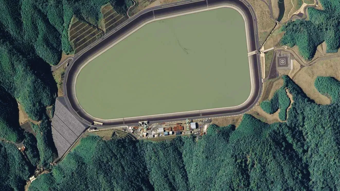
Pumped storage moves water between an upper and a lower reservoir: pumping when power is cheap, generating when it is needed. It is the lowest-cost way to store many hours of energy at utility scale, but each unit takes time to start, change mode and has a minimum pumping load.
A battery beside the pumped storage plant fills those gaps: it answers in milliseconds, covers mode-change times, absorbs small surpluses that are below a pump's minimum and provides grid-forming support.
3.1How the two complement each other
| Feature | Battery (Li-ion) | Pumped storage | Hybrid result |
|---|---|---|---|
| Response | < 1 s | Seconds (running) to minutes (from standstill) | Fast overall response |
| Economic duration | 1–4 h | 6–12 h or more | Covers 1–12 h+ |
| Round-trip efficiency | ≈ 85–92 % (AC) | ≈ 75–82 % | Weighted by use |
| Life | 10–20 years, cells augmented | 50–80 years civil, 30–40 years machines | Long asset life |
| Minimum load | None | Fixed-speed pump runs only at full load | Battery takes small surpluses |
| Build time | 6–18 months | 4–7 years | Battery earns revenue early |
3.2What the battery does for the pumped storage plant
Operational
5- Bridges start-up and pump-to-turbine changeover
- Takes fast frequency response so turbines move smoothly
- Absorbs solar surpluses smaller than one pump
- Supplies black-start power to the station
- Reduces wear from frequent start-stops
Commercial
5- Earns ancillary-service revenue
- Lets the plant meet a tighter delivery profile
- Can be built first and earn while the dam is built
- Reduces penalties during unit outages
- Allows a smaller number of variable-speed units
3.3Layout choices
- Co-located: battery in the pumped-storage switchyard, sharing the transformer and line
- Same pooling station: battery at the solar or wind pooling point, PSP elsewhere on the same contract
- Fixed-speed pumps + battery instead of costlier variable-speed units, where studies allow
- Off-river (closed-loop) PSP with battery at the solar park — common in Indian hybrid parks
- Battery sized at 10–30 % of PSP power for support, or larger where it also carries peaks
- Common EMS and one scheduling point towards the load despatch centre
Figures are typical ranges from public literature for Li-ion BESS and modern reversible Francis units; actual values depend on design, head and operating regime.
Section 04
Battery + Thermal Storage Hybrid
Thermal storage keeps energy as heat in molten salt, sand, crushed rock, concrete or pressurised water. It is cheap per MWh of heat, but turning heat back into electricity loses a lot (often 35–60 % comes back). It is most valuable when the heat itself is needed — for process steam, drying or hot oil.
A battery handles the electrical peaks and grid services; the thermal store takes the bulk energy, either as heat delivered to a process or as heat run through a steam or gas turbine later (the so-called Carnot battery).
4.1Ways to pair battery and heat
01
IndustryBattery + electric boiler + heat store
Cheap midday solar charges a heat store through resistive or electrode heaters; the factory draws steam at night. The battery serves electrical loads.
02
UtilityCSP + battery
Concentrated solar heats molten salt for evening generation; PV with battery covers daytime and fast response.
03
GridCarnot battery + BESS
Electricity to heat (or heat pump) to heat back to power through a turbine; battery handles the first hours and ramps.
04
BuildingsHeat pump + hot water store + battery
High efficiency for low-temperature heat; battery shifts the heat pump's electricity use.
05
IndustryWaste heat recovery + store
Recovered heat from furnaces or engines stored between shifts; battery covers motor and drive peaks.
06
RetrofitThermal plant + BESS
A battery beside a coal or gas unit gives fast response so the unit can run steadier and at lower minimum load.
4.2Common heat-storage media
| Medium | Temperature range | Typical use | Notes |
|---|---|---|---|
| Pressurised water / steam accumulator | 100–250 °C | Process steam buffering | Quick discharge, mature |
| Thermal oil | Up to ≈ 300–400 °C | Hot-oil processes | Fire risk managed by design |
| Molten nitrate salt | ≈ 290–565 °C | CSP, power cycles | Freeze protection needed |
| Sand / crushed rock / concrete | Up to ≈ 600–1,000 °C | Industrial heat, Carnot batteries | Low-cost media, larger volume |
| Phase-change materials | Set by material | Compact heat and cold | Higher cost per kWh |
4.3Heat stored in a sensible-heat tank
Sensible heat
Q = m × cp × ΔT
e.g. 1,000 t molten salt × 1.5 kJ/kg·K × 270 K ≈ 405,000 MJ ≈ 112 MWh(th)
Heat stored equals mass times specific heat times the temperature swing. Only part of this comes back as electricity; for process heat almost all can be used.
| Symbol | Meaning |
|---|---|
| m | Mass of storage medium, kg |
| cp | Specific heat, kJ/kg·K |
| ΔT | Hot minus cold temperature, K |
Temperatures, efficiencies and specific heats are indicative literature values; see the Thermal Storage page for full detail.
Section 05
Battery + Hydrogen Hybrid
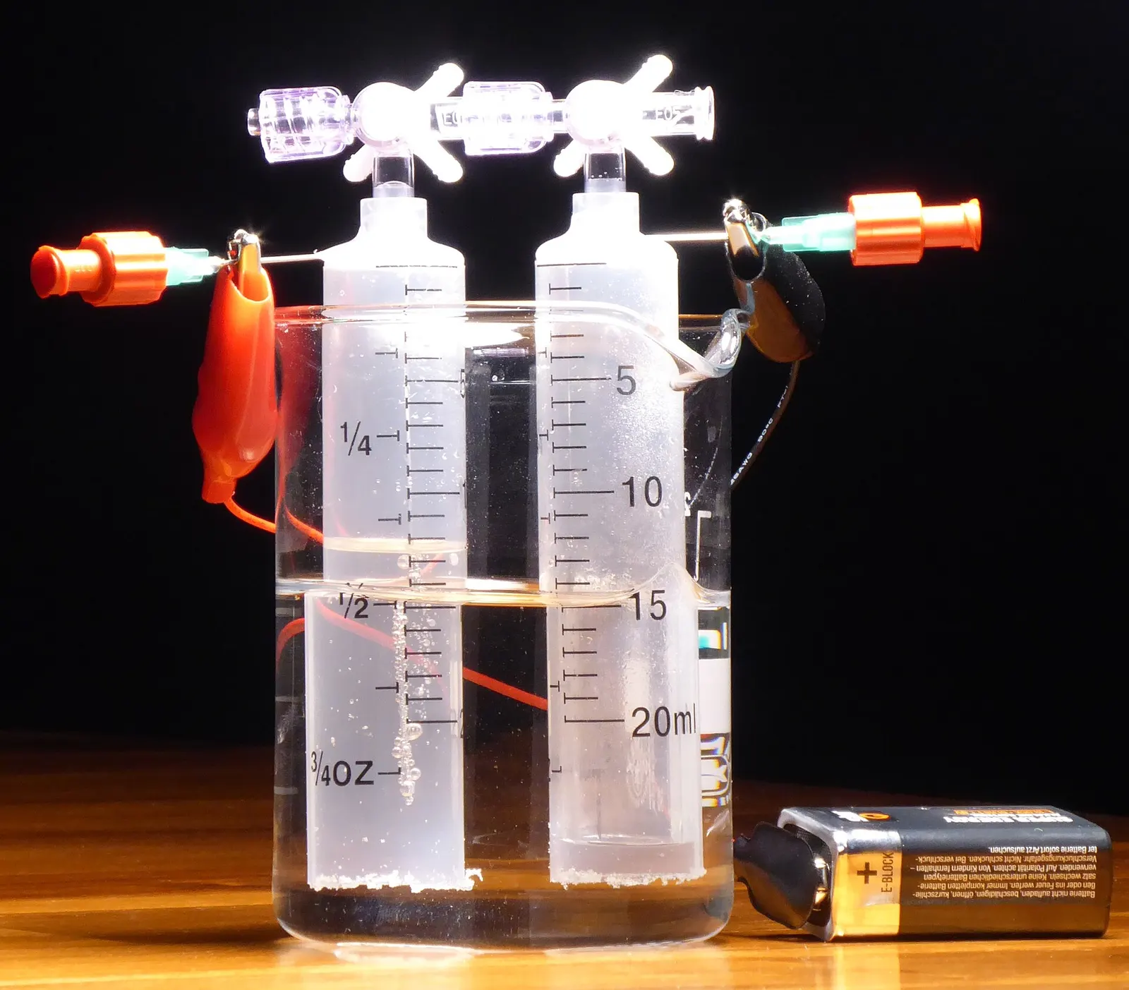
Hydrogen made by electrolysis can be stored for weeks or months in tanks, pipelines or salt caverns, and turned back into electricity in fuel cells or hydrogen-ready turbines. The round trip is poor — typically 30–45 % of the electricity comes back — so hydrogen is used for long gaps, not daily cycles.
The battery does the daily cycling and keeps the electrolyser running smoothly when solar and wind fluctuate; hydrogen covers the long, rare gaps or is sold to industry as a product.
5.1Power-to-hydrogen-to-power chain
- Solar / wind
- Battery smooths supply
- Electrolyser (≈ 50–55 kWh/kg)
- Compression & storage
- Fuel cell or H₂ turbine
- Firm power or H₂ sales
5.2Division of labour
| Duty | Battery | Hydrogen |
|---|---|---|
| Seconds to minutes balancing | Yes | No — electrolysers and fuel cells ramp more slowly and wear with cycling |
| Daily solar shifting | Yes, efficient | Possible but wasteful |
| Multi-day low-wind spells | Too costly | Yes |
| Seasonal storage | No | Yes, with caverns or large tanks |
| Industrial feedstock | No | Yes — ammonia, steel, refining |
| Electrolyser load smoothing | Keeps stack within its preferred load band | — |
5.3Design points
- Electrolyser type (alkaline or PEM) sets how fast it can follow renewables
- Battery sized to cover electrolyser minimum load at night or in clouds
- Storage pressure and vessel type under PESO rules
- Fuel cell or turbine sized for the firm power gap, not the full plant
- Water supply and treatment (≈ 9–10 litres of pure water per kg H₂, more raw water)
- Selling hydrogen often pays better than burning it back to power
Electrolyser energy use and round-trip figures are typical published ranges; see the Hydrogen Storage page and its live estimator for more detail.
Section 06
Supercapacitor + Battery Hybrid
Supercapacitors (also called ultracapacitors) store energy in an electric field. They hold little energy but can deliver or absorb very high power hundreds of thousands of times without wearing out. Batteries hold far more energy but age faster under sharp, frequent spikes.
Pairing them lets the supercapacitor take the spikes — a crane lowering a load, a train braking, a gust on a wind turbine — while the battery supplies the steady energy.
6.1Supercapacitor and battery side by side
| Property | Supercapacitor | Li-ion battery |
|---|---|---|
| Energy density | ≈ 3–10 Wh/kg | ≈ 150–250 Wh/kg (cell) |
| Power density | Very high, ≈ 5–15 kW/kg | Lower, ≈ 0.3–3 kW/kg |
| Cycle life | ≈ 500,000 – 1,000,000+ | ≈ 3,000–10,000 |
| Useful time-scale | Milliseconds to ≈ 30 s | Minutes to hours |
| Efficiency | ≈ 95–98 % | ≈ 90–95 % (DC) |
| Temperature tolerance | Wide | Narrower, needs cooling |
6.2Where the pairing is used
01
Ports and cranes
Energy from lowering containers is caught and reused; diesel or grid peaks are cut.
02
Metro and rail
Braking energy recovered at the trackside; battery supports longer gaps between trains.
03
Wind and solar plants
Fast smoothing and fault ride-through support; battery for longer ramps.
04
Weak or island grids
Fast frequency response and motor starting; battery for energy.
05
Industrial drives
Welding, presses and arc furnaces with sharp load spikes.
06
Data centres and UPS
Ride-through for the seconds before generators start.
6.3Usable energy of a supercapacitor bank
Capacitor energy
E = ½ × C × (V1² − V2²)
e.g. 1 MW for 10 s = 10 MJ ≈ 2.8 kWh; at 800 V max and 400 V min this needs C ≈ 10,000,000 / (0.5 × 480,000) ≈ 42 F
Energy depends on the square of voltage, so letting voltage fall to half of maximum uses 75 % of the stored energy. The DC/DC converter keeps the bus steady while the bank voltage swings.
| Symbol | Meaning |
|---|---|
| C | Capacitance, farads |
| V1 | Maximum voltage, V |
| V2 | Minimum voltage, V |
Density, power and cycle figures are typical published ranges for commercial cells; see the Electrical Storage page and its supercapacitor estimator.
Section 07
Battery + Cold Storage Hybrid
In hot climates cooling is often 40–60 % of a building's electricity and most of its peak. Making ice or chilled water at night (or at midday from solar) and melting it in the afternoon shifts that load cheaply — cold storage costs far less per kWh than a battery for the same cooling job.
The battery covers the non-cooling loads, the chiller start-up spikes and any backup duty; the cold store carries the cooling hours.
7.1Typical campus system
Cold side
4- Chillers sized for night charging
- Ice tanks or stratified chilled-water tank
- Heat exchangers and pumps
- Building management system link
Electrical side
4- Rooftop or open-access solar
- Battery for peak shaving and backup
- Demand-charge management
- Diesel-generator reduction
Controls
4- Time-of-day tariff schedule
- Weather and occupancy forecast
- Joint dispatch of chiller and battery
- Maximum-demand limit
7.2Cold store vs battery for the same cooling shift
| Aspect | Ice / chilled water | Battery running the chiller |
|---|---|---|
| Cost per kWh of cooling shifted | Low | Several times higher |
| Life | 20–30 years tanks | 10–15 years cells |
| Flexibility | Cooling only | Any electrical load |
| Space | Large tanks | Compact |
| Backup during outages | Cooling only, with pumps on backup | Yes |
7.3Cooling stored as ice
Latent cold
Q = m × 334 kJ/kg; 1 TR·h ≈ 3.517 kWh(th) ≈ 12,660 kJ
e.g. 2,000 TR·h ≈ 7,034 kWh(th) needs about 76 t of ice
Freezing water stores about 334 kJ per kg. Ice is roughly six to eight times more compact than chilled water at a 6–8 K temperature swing. See the Cold Storage page and its estimator.
| Symbol | Meaning |
|---|---|
| TR·h | Tonne of refrigeration for one hour |
| m | Mass of ice, kg |
Section 08
Round-the-Clock and Firm, Dispatchable Renewable Power
India's buyers increasingly ask for renewable power that behaves like a conventional plant: a set profile, high availability and penalties for shortfall. The Ministry of Power issued guidelines for RTC power (2020) and for firm and dispatchable renewable energy, FDRE (2023), and agencies such as SECI, NTPC, NHPC and SJVN run such tenders.
A hybrid of solar, wind, batteries and pumped storage is usually the lowest-cost way to meet these profiles; the design is a large optimisation problem over many weather years.
8.1A typical RTC / FDRE plant
- Solar (day)
- Wind (evening and night)
- Battery (fast balancing, peaks)
- Pumped storage (bulk hours)
- Hybrid EMS + PPC
- Firm profile to the buyer
8.2Common tender structures
| Structure | What is promised | Storage role |
|---|---|---|
| RTC | Power across the day with a minimum annual availability (early tenders ≈ 80–85 %) | Fill night and low-wind hours |
| FDRE — assured peak | Firm supply in buyer-declared peak hours with high availability (often ≈ 90 %) | Large energy in a few peak hours |
| FDRE — demand following | Follow the buyer's hourly load profile | Shape and shift every day |
| Solar / wind + storage | Set storage hours (e.g. 2–4 h) of the renewable capacity | Battery-dominant |
| Standalone storage (BESS / PSP) | Capacity on call, charged by the buyer | Pure storage tolling |
8.3What the design must prove
- Availability in the required hours across many weather years, not one typical year
- Battery degradation and an augmentation plan over the contract term
- Pumped-storage or long-duration availability, outages and maintenance windows
- Transmission (ISTS / InSTS) connectivity, GNA and losses
- Penalties and compensation for shortfall, and the value of excess energy
- Sensitivity to cost of capital, equipment prices and tariff
8.4How a bid model is built
- 1Load 10–20 years of hourly (or 15-minute) solar and wind data for candidate sites
- 2Encode the tender profile, availability rules and penalties
- 3Choose candidate solar, wind, battery and long-duration sizes
- 4Run a dispatch optimisation for every year and size combination
- 5Pick the lowest tariff that meets availability with a safety margin
- 6Stress-test with weak wind years, outages and degradation
Availability levels, penalties and incentives differ between tenders and are revised; figures above are indicative. Always read the current tender documents and Ministry of Power guidelines.
Section 09
Industrial and Campus Microgrids
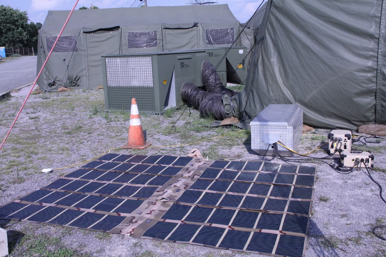
Factories, mines, ports, data centres and campuses can combine electrical, heat and cold storage with on-site solar, wind and backup generation. One system then cuts the power bill, the fuel bill and the peak demand, and can keep critical loads running when the grid fails.
In a microgrid the battery's inverter often becomes grid-forming when the site islands — it sets voltage and frequency itself, the job a diesel generator used to do.
9.1Typical industrial hybrids
01
Battery + heat storage
Cheap power stored as steam or hot oil for process heat; battery for electrical peaks.
02
Battery + cold storage
Ice or chilled water carries cooling; battery carries the rest of the load.
03
Waste heat + thermal store
Recovered heat stored and reused across shifts.
04
Captive solar + battery
Rooftop, ground-mount or open-access solar firmed for daytime and evening use.
05
Islanding microgrid
Grid-forming inverters, fast transfer switch and generator backup for critical loads.
06
Electrolyser + battery
Battery smooths renewable supply to keep electrolysers in their efficient range.
9.2Where the savings come from
Bill savings
4- Time-of-day energy shifting
- Maximum-demand (kVA) charge reduction
- Higher self-use of captive solar
- Lower diesel use and fuel logistics
Reliability
4- Ride-through of grid dips and outages
- Power-quality correction (harmonics, flicker)
- Soft start of large motors
- Black start of the site after a trip
9.3Indicative sizes by site type
| Site | Peak load | Typical hybrid |
|---|---|---|
| Commercial campus | 1–10 MW | Solar + 1–4 h battery + ice store |
| Data centre | 5–100 MW | Battery UPS + supercaps + chilled water + generators |
| Process industry | 10–100 MW | Solar / wind open access + battery + heat store |
| Remote mine or island | 1–50 MW | Solar / wind + battery + diesel or H₂ backup |
| Port | 5–30 MW | Battery + supercap for cranes + shore power |
Load ranges are indicative; each site needs a load study from metered data.
Section 10
System Architecture and Configurations
A hybrid can be joined at different points: on a shared DC bus, on the AC side of each inverter, at the plant substation, or only on paper through a common contract and scheduling. The choice changes cost, losses, controllability and how the grid connection is approved.
10.1Coupling options
| Option | How it is joined | Pros | Cons |
|---|---|---|---|
| DC-coupled | Battery on the PV inverter's DC bus via DC/DC converter | Captures clipped solar, fewer conversions | Tied to the PV inverter size |
| AC-coupled | Separate inverters joined on the MV collection bus | Flexible, easy to add later | One more conversion stage |
| Substation-coupled | Each technology has its own transformer bay at the plant substation | Clear metering, separate O&M | More switchgear |
| Multi-site (virtual) | Different sites, one contract and one scheduling point | Uses best site for each technology | Transmission charges and losses |
| Multi-port converter | One converter with battery, supercap and PV ports | Compact for industrial use | Fewer suppliers, smaller sizes |
10.2Main components
Storage
4- Battery containers (cells, modules, racks, BMS)
- Pumped-storage units or thermal / H₂ plant
- Supercapacitor modules
- Heating, cooling and fire systems
Power conversion
4- Bidirectional inverters (PCS)
- DC/DC converters
- MV transformers and RMUs
- Main power transformer and switchyard
Control
4- Hybrid EMS
- Power plant controller
- SCADA and RTUs
- Metering, protection and communications
10.3Simplified single-line path (AC-coupled)
- Battery racks + BMS
- PCS (DC → AC)
- MV transformer 0.69/33 kV
- 33 kV collection bus
- Plant transformer 33/220 or 400 kV
- Grid substation
10.4Civil and mechanical scope
- Battery and PCS foundations, cable trenches, roads and drainage
- Fire separation distances or walls between containers
- Pumped-storage dams, tunnels, powerhouse (see the Pumped Storage page)
- Thermal tanks, foundations with insulation and cooling
- Hydrogen vessel yards with hazardous-area zoning
- Control building, SCADA room and switchyard
Section 11
Hybrid Energy Management, Plant Control and SCADA
The energy management system decides, minute by minute, which store charges, which discharges and by how much. Below it the power plant controller turns those decisions into fast set-points for every inverter and unit, and SCADA records and reports everything.
Grid-forming inverters are the newest piece: instead of following the grid's voltage, they create it, which helps weak grids and allows islanding.
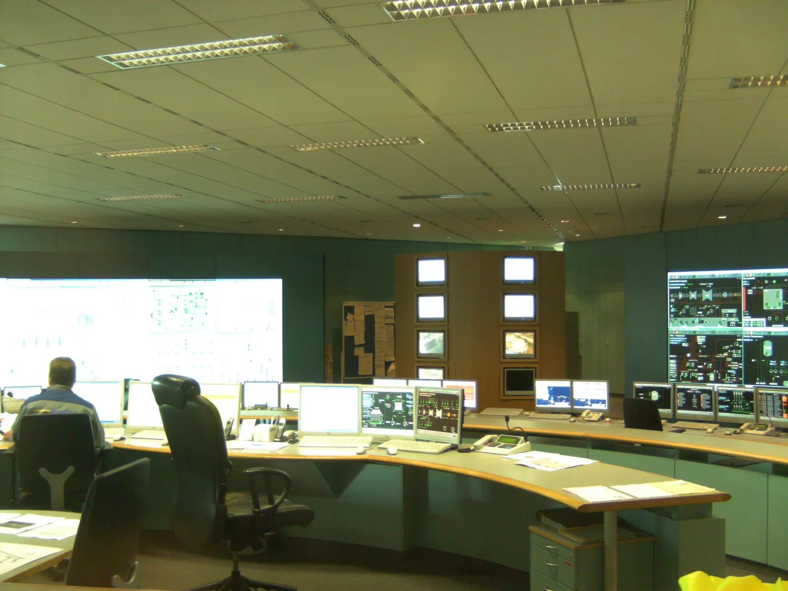
11.1Control layers
| Layer | Time-scale | Job |
|---|---|---|
| Market / scheduling EMS | Day-ahead, 15-min blocks | Bids, schedules, SoC plans across stores |
| Real-time EMS | Seconds to minutes | Split power between stores, track schedule |
| Power plant controller | 100 ms – 1 s | Active / reactive power, voltage and frequency control at the meter |
| Inverter / unit controls | Milliseconds | Current control, grid-forming, protection |
| BMS and unit protection | Milliseconds | Cell and machine safety limits |
11.2Functions, equipment and digital tools
Control functions
5- Power split by frequency band
- State-of-charge management across stores
- Forecast-based scheduling
- Market and tariff optimisation
- Degradation-aware dispatch
Equipment
5- Hybrid EMS and power plant controller
- Multi-source converters
- Grid-forming inverters
- Microgrid controllers
- Integrated SCADA to IEC 61850
Digital
5- Weather and load forecasting
- Digital twin of the plant
- Performance and degradation analytics
- Cyber-security to IEC 62443
- Remote monitoring centre
11.3Grid-following vs grid-forming inverters
| Aspect | Grid-following | Grid-forming |
|---|---|---|
| Behaviour | Measures grid voltage and injects current | Acts as a voltage source, like a generator |
| Weak grids | Can become unstable | Stabilises the grid |
| Inertia-like response | Only through added control | Natural, instant |
| Islanding / black start | Not without another source | Yes |
| Maturity | Standard | Growing fast; grid codes being written |
11.4Digital and AI tools
01
Forecasting
Machine-learning forecasts of solar, wind, load and prices feed the scheduler.
02
Digital twin
A plant model checks schedules, predicts degradation and tests control changes before they go live.
03
Predictive maintenance
Cell, inverter and pump-turbine data flag faults before they trip the plant.
Section 12
Grid Integration and Grid-Code Compliance
A hybrid plant must meet the grid code at its connection point as one plant: voltage and frequency ride-through, reactive power, ramp limits, protection and data to the load despatch centre. In India this means the CEA connectivity standards, the CERC Indian Electricity Grid Code (IEGC 2023) and the rules of Grid-India and the state load despatch centres.
12.1Studies usually required
Steady state
4- Load flow and losses
- Reactive power capability
- Short-circuit levels
- Voltage profile
Dynamic
4- Fault ride-through (LVRT / HVRT)
- Frequency response
- Small-signal stability
- EMT studies for weak grids
Quality and protection
4- Harmonics and flicker
- Protection coordination
- Insulation coordination
- Earthing
12.2Connection steps in India (ISTS case)
- 1Apply for connectivity / GNA with the Central Transmission Utility
- 2Submit plant data and simulation models
- 3Agree the bay, metering and communication scheme
- 4Build the dedicated line and bay
- 5Model validation and grid-code compliance tests
- 6Trial operation and declaration of commercial operation
12.3Points special to hybrids
- Connection capacity may be less than the sum of the parts — the EMS limits export
- Storage charging from the grid needs its own metering and tariff treatment
- Separate metering for each technology where incentives differ
- One scheduling point for the combined plant where the contract allows
- Validated models for every inverter type in the plant
Connectivity regulations and charge waivers change; check the current CERC, CEA and Ministry of Power orders for each project.
Section 13
Designing and Sizing a Hybrid
The design question is how many MW and MWh each technology should carry for the lowest lifetime cost while still meeting the delivery profile. The battery takes the first hours and every fast swing; the long-duration store takes the remaining hours at a lower cost per MWh of capacity.
The formulas below give first estimates. A bankable design always uses an hourly or sub-hourly simulation.
13.1Design steps
- 1Define the delivery profile and availability
- 2Run an hourly or sub-hourly simulation of supply and demand
- 3Split the duty into fast, daily and long-duration bands
- 4Size each technology for its band
- 5Optimise for lifetime cost per delivered MWh
- 6Design the common grid connection and controls
- 7Plan augmentation and replacements
13.2Energy split
Battery and long-duration energy
E(battery) = P × h(battery); E(long) = P × (H − h(battery))
e.g. 100 MW firm for 10 h with 2 h of battery: 200 MWh battery + 800 MWh pumped storage
P is the firm power, H the firm hours each day and h(battery) the hours given to the battery. The example is illustrative only; real plants also carry margins for losses and degradation.
| Symbol | Meaning |
|---|---|
| P | Firm power, MW |
| H | Firm hours per day |
| h(battery) | Hours carried by the battery |
13.3Capital cost of the split
Capex comparison
C(hybrid) = E(battery) × c(battery) + E(long) × c(long); C(all-battery) = P × H × c(battery)
e.g. 200 MWh × ₹1.6 cr + 800 MWh × ₹0.9 cr = ₹1,040 crore vs 1,000 MWh × ₹1.6 cr = ₹1,600 crore
Costs per MWh are illustrative. For long-duration stores the cost per MWh falls as hours increase because the turbines or converters are a fixed cost, so the per-MWh figure must match the chosen duration.
| Symbol | Meaning |
|---|---|
| c(battery) | Battery installed cost, ₹ crore/MWh |
| c(long) | Long-duration installed cost, ₹ crore/MWh at that duration |
13.4Charging energy needed
Energy in
E(in) = E(battery) / η(battery) + E(long) / η(long)
e.g. 200 / 0.88 + 800 / 0.78 ≈ 227 + 1,026 ≈ 1,253 MWh of surplus solar or wind each day
The renewable plant must produce this surplus on top of what it delivers directly. Lower round-trip efficiency on the long store means more solar or wind must be built.
| Symbol | Meaning |
|---|---|
| η | Round-trip efficiency of each store |
13.5Battery size at beginning of life
Degradation margin
E(BOL) = E(required) / (SoH(EOL) × DoD)
e.g. 200 MWh / (0.80 × 0.95) ≈ 263 MWh installed, or less installed with planned augmentation
Batteries lose capacity with age. Either install extra at the start or add modules later (augmentation); the cheaper path depends on falling cell prices and contract terms.
| Symbol | Meaning |
|---|---|
| SoH(EOL) | State of health at end of the period, e.g. 0.80 |
| DoD | Usable depth of discharge |
13.6Live estimator
Enter the firm power (MW), the firm hours needed each day, how many of those hours the battery carries, and the installed cost per MWh of the battery and of the long-duration store (₹ crore/MWh). The estimator gives the battery MWh, the long-duration MWh, the capital cost of each and the hybrid total compared with doing the whole job with batteries alone. It is a first-pass split and does not include efficiency losses, degradation margins or grid costs.
Estimate
- Battery energy
- 400 MWh
- Long-duration energy
- 800 MWh
- Hybrid capex
- ₹1,120 crore
- All-battery capex
- ₹1,680 crore
- Difference
- saves ₹560 crore
Illustrative capex only: enter your own cost figures. Ignores efficiency, degradation, augmentation and the long-duration plant's own power cost. Preliminary screening only; BARREL confirms any figure with a site study.
All costs, efficiencies and degradation figures here are indicative examples from public literature and recent Indian tenders; they move with cell prices, interest rates and site conditions.
Section 14
Engineering Deliverables Register
A hybrid project produces the deliverables of each technology plus an extra layer for integration. The register below lists the usual documents from concept to handover.
14.1Typical deliverables
| Stage | Deliverable | Purpose |
|---|---|---|
| Concept | Profile and resource study, multi-year simulation | Choose technologies and sizes |
| Concept | Pre-feasibility report and cost estimate | Go / no-go |
| Feasibility | Detailed project report (DPR) | Financing and approvals |
| Feasibility | Grid connection studies and models | Connectivity approval |
| Basic design | Single-line diagrams, layouts, control philosophy | Tender specifications |
| Basic design | EMS functional specification and use-case list | Controls procurement |
| Detailed design | Protection, cable, earthing and lightning studies | Construction drawings |
| Detailed design | Fire and hazard studies (HAZID, HAZOP, fire risk) | Safety approvals |
| Detailed design | Civil and structural design, geotechnical reports | Foundations and works |
| Testing | FAT / SAT procedures, commissioning plan | Acceptance |
| Handover | As-built drawings, O&M manuals, digital twin | Operation |
14.2Integration-specific documents
- Interface matrix between OEMs (signals, protocols, responsibilities)
- Control hierarchy and fallback modes
- Integrated performance guarantee test procedure
- Hardware-in-the-loop test report for the EMS
- Cyber-security architecture and zoning
- Augmentation and replacement plan
The list is typical; the lender's engineer and the buyer may require more.
Section 15
Site Selection and Feasibility
A hybrid's sites are chosen technology by technology: the battery near the solar or wind pooling station, the pumped storage where there is head and water, thermal or hydrogen near the industrial user. Feasibility then checks that the combined plant can be connected, built and financed.
15.1Site criteria by technology
Battery
4- Flat land near the pooling substation
- Ambient temperature and dust
- Flood-free ground
- Fire separation and access for fire services
Pumped storage
4- Head of 100–700 m over short distance
- Geology for dams and tunnels
- Water for first fill and losses
- Forest, wildlife and resettlement impacts
Thermal / hydrogen / cold
4- Nearby heat, cold or hydrogen user
- Water supply for electrolysers
- PESO safety distances
- Industrial zoning
15.2Feasibility sequence
- 1Desk screening of resource, land, grid and water
- 2Site visits and topographic survey
- 3Geotechnical and, for PSP, geological investigation
- 4Hybrid simulation and optimum sizing
- 5Grid connectivity study and application
- 6Environmental and social screening
- 7Cost estimate, financial model and risk register
15.3Typical approvals in India
| Approval | Authority (typical) | Applies to |
|---|---|---|
| Connectivity / GNA | CTU or state transmission utility | All grid-connected plants |
| DPR concurrence | CEA (with CWC, GSI inputs) | Pumped storage above set thresholds |
| Environment and forest clearance | MoEFCC and state | Pumped storage, large civil works |
| Explosives / pressure vessel licences | PESO | Hydrogen and pressurised storage |
| Fire NOC | State fire service | Battery and industrial sites |
| Electrical inspection | CEA or state electrical inspector | All electrical installations |
Approval routes depend on state, size and location; the table is a general guide only.
Section 16
Turnkey EPC for Hybrid Plants
Hybrid projects most often go wrong at the interfaces — between the battery supplier and the inverter supplier, between the EMS and the pumped-storage governor, between the plant and the grid. A single EPC wrap with clear interface management removes most of that risk for the owner.
BARREL can take single-point responsibility for the integrated plant, working with OEM partners for each technology.
16.1Project phases
- 1Concept, simulation and bid support
- 2Feasibility, DPR and approvals
- 3Basic design and procurement strategy
- 4Detailed engineering and OEM selection
- 5Manufacturing, FAT and logistics
- 6Civil and electrical construction
- 7Integrated commissioning and grid tests
- 8Performance test, COD and handover
16.2Typical work packages
| Package | Scope |
|---|---|
| Battery | Cells, racks, BMS, containers, HVAC, fire systems |
| Power conversion | PCS, DC/DC, MV transformers, RMUs |
| Long-duration store | PSP civil and electro-mechanical, or thermal / H₂ plant |
| Electrical BoP | Collection system, switchyard, plant transformer, line |
| Controls | EMS, PPC, SCADA, communications, cyber-security |
| Civil BoP | Roads, drainage, foundations, buildings, fencing |
16.3Delivery models
01
Full EPC (turnkey)
One contractor for design, supply, build and performance; simplest for the owner and lenders.
02
Split EPC
Separate packages for each technology with an owner's engineer integrating; lower price, more interface risk.
03
EPCM
The engineer manages many contractors for the owner; flexible but the owner carries more risk.
16.4What the integrator guarantees
- Delivered profile and availability at the meter
- Round-trip efficiency of the combined plant
- Grid-code compliance and model validation
- Battery capacity retention with augmentation
- Schedule and liquidated damages
- Long-term O&M with availability reporting
Section 17
Equipment, Supply Chain and Manufacturing in India
India is building its own battery cell, inverter and transformer manufacturing under the production-linked incentive (PLI) scheme for advanced chemistry cells and other programmes. Pumped-storage turbines, generators and gates are already made in India; electrolysers and fuel cells are being localised.
BARREL can source equipment through OEM partners, with factory inspection and a preference for domestic content where tenders require it.
17.1Key equipment and sourcing
| Equipment | Main options | India status (indicative) |
|---|---|---|
| Battery cells | LFP (most common), NMC, sodium-ion emerging | Cell plants ramping under PLI; modules and packs made locally |
| Battery containers / BMS | 20 ft or 40 ft liquid-cooled units | Several Indian assemblers |
| PCS / inverters | Central and string, grid-forming options | Manufactured in India |
| Transformers and switchgear | MV and HV | Strong domestic base |
| Pump-turbines and generators | Fixed or variable speed | Domestic manufacture of fixed-speed units; variable speed mostly imported |
| Electrolysers / fuel cells | Alkaline, PEM | Localisation under national hydrogen programme |
| Supercapacitors | Modules and racks | Mostly imported |
17.2Supply-chain checks
- Cell origin, chemistry and test certificates
- BIS registration where the product is notified
- Domestic content rules in the tender
- Approved List of Models and Manufacturers where it applies
- Lead times for transformers and HV switchgear
- Warranty terms and spare-parts stock in India
Manufacturing status changes quickly; check the latest MNRE, MHI and BIS notices before procurement.
Section 18
Testing, Commissioning, Operations and Maintenance
Each technology is tested on its own first, then the whole plant is tested together under the EMS. The integrated tests are what prove the hybrid can deliver its profile and meet the grid code.
In operation, a hybrid is mostly about dispatch: keeping every store at the right state of charge for what is coming next. Maintenance windows must be planned so that the remaining stores can still cover the contract.
18.1Commissioning sequence
- 1Factory acceptance tests (FAT) of batteries, PCS, EMS
- 2EMS hardware-in-the-loop test with plant models
- 3Site acceptance tests (SAT) of each subsystem
- 4Energisation of transformers and switchyard
- 5Individual store tests: capacity, efficiency, ramp
- 6Integrated EMS tests: power split, SoC management, fallbacks
- 7Grid-code compliance tests with the load despatch centre
- 8Profile-delivery performance test and COD
18.2Key performance tests
| Test | What it shows |
|---|---|
| Capacity test (MWh) | Usable energy at rated power |
| Round-trip efficiency | Energy out / energy in at the meter |
| Response time and ramp | Speed of fast store and hand-over to slow store |
| Fault ride-through and reactive power | Grid-code compliance |
| Islanding and black start (if required) | Grid-forming capability |
| Profile delivery run (days) | The hybrid meets the contract shape |
Test procedures follow the contract, IEC 62933 and the grid operator's requirements; O&M intervals follow the OEM manuals.
18.3Typical O&M tasks
Daily
4- Schedule submission and revision
- SoC planning across stores
- Alarm handling
- Performance reporting
Periodic
4- Battery capacity checks and balancing
- HVAC, fire-system and inverter maintenance
- Pump-turbine or thermal plant inspection
- Thermography and cable checks
Long-term
4- Battery augmentation
- Inverter and cell replacement
- Major overhauls of PSP units
- Control-software updates
18.4Key performance indicators
| KPI | Meaning |
|---|---|
| Contract availability | Share of required hours delivered |
| Round-trip efficiency | Energy out over energy in |
| Battery state of health | Remaining capacity vs new |
| Equivalent full cycles | Battery throughput per year |
| Forced outage rate | Unplanned unavailability of each store |
| Deviation charges | Penalties for missing schedule |
18.5Hybrid-specific practices
- Stagger maintenance of different stores
- Keep a reserve SoC margin before peak hours
- Track battery cycling to protect the warranty
- Re-tune EMS after augmentation or unit changes
Section 19
Safety, Risk and Environment
A hybrid brings together the hazards of each technology: thermal runaway in batteries, dam and tunnel risks in pumped storage, hot fluids in thermal stores and flammable gas in hydrogen systems. Each needs its own protection, and the layout must keep one hazard from triggering another.
19.1Main hazards and controls
| Technology | Hazard | Controls |
|---|---|---|
| Battery | Thermal runaway, fire, off-gas | BMS, cell-level detection, gas detection, deflagration venting, spacing, tested per UL 9540A |
| Supercapacitor | High DC voltage, electrolyte | Insulation, discharge circuits, enclosure |
| Pumped storage | Dam failure, flooding, tunnel collapse | Dam safety design and monitoring, emergency action plan |
| Thermal store | Burns, hot salt or oil leaks | Insulation, leak containment, fire protection |
| Hydrogen | Leaks, fire, explosion | Hazardous-area zoning, ventilation, detection, PESO-licensed vessels |
| Electrical | Arc flash, shock | Protection design, earthing, safe work procedures |
19.2Environment and circularity
01
Battery recycling
India's Battery Waste Management Rules, 2022 set producer responsibility for collection and recycling.
02
Land and water
Off-river PSP limits river impacts; hydrogen plants need water planning.
03
Lifecycle carbon
Long-lived civil stores have low lifecycle emissions per MWh delivered.
04
Second life
Used EV or grid batteries can serve lighter duty before recycling.
05
Materials
LFP and sodium-ion avoid cobalt and nickel.
06
Noise and visual
Cooling fans and transformers need setback from homes.
Safety distances and protection depend on chemistry, size and local rules; a site-specific risk assessment is required.
Section 20
Standards and Compliance
There is no single standard for a hybrid. Each technology follows its own codes, and the integrated plant follows the grid code and storage-system standards.
20.1International standards (examples)
| Standard | Subject |
|---|---|
| IEC 62933 series | Electrical energy storage systems — terms, performance, safety, environment |
| IEC 62619 / IEC 62620 | Safety and performance of industrial lithium cells and batteries |
| IEC 62477-1 | Safety of power electronic converter systems |
| UL 9540 / UL 9540A | Energy storage system safety and fire propagation testing |
| NFPA 855 | Installation of stationary energy storage systems |
| IEC 61850 | Communication in substations and power plants |
| IEC 62443 | Industrial cyber-security |
| IEEE 1547 / IEEE 2800 | Interconnection of distributed and inverter-based resources |
| ISO 22734 / IEC 62282 | Hydrogen electrolysers / fuel cells |
20.2India — regulations and codes
| Instrument | Subject |
|---|---|
| CEA Technical Standards for Connectivity to the Grid | Plant connection requirements incl. storage |
| CEA safety and electric supply regulations | Electrical safety |
| CERC Indian Electricity Grid Code 2023 | Scheduling, ancillary services, grid operation |
| Ministry of Power RTC and FDRE bidding guidelines | Tender structure for firm renewable supply |
| Ministry of Power pumped storage guidelines (2023) | Development of PSP |
| Dam Safety Act, 2021 | Dam surveillance and safety |
| PESO rules (SMPV, gas cylinders) | Hydrogen and pressurised gases |
| BIS standards (IS / IEC adoptions) | Product safety and quality |
| Battery Waste Management Rules, 2022 | End-of-life batteries |
Standards and regulations are revised often; the lists are examples, not a complete compliance plan. Check the current editions on the IEC webstore, BIS and CEA websites.
Section 21
Commercial Models, Revenue, Cost and Investment Risk
A hybrid earns money in several ways at once — a firm-power tariff, a storage capacity fee, market arbitrage, ancillary services and industrial bill savings. Its cost is the sum of each technology's cost plus integration, but its value comes from the combined product.
21.1Indicative installed costs (India)
| Item | Indicative range | Comment |
|---|---|---|
| Battery (2–4 h, utility, turnkey) | ≈ ₹1.2–2.2 crore/MWh | Falling with cell prices |
| Pumped storage (6–10 h) | ≈ ₹0.6–1.2 crore/MWh (≈ ₹5–8 crore/MW) | Site-specific, long build |
| Thermal store (heat) | Low per MWh(th) | Plus heaters and power block if needed |
| Hydrogen chain | High per MW | Electrolyser, storage and fuel cell all add up |
| Integration (EMS, BoP, grid) | ≈ 5–15 % of project | Depends on coupling |
21.2Levelised cost of storage
LCOS
LCOS = (CAPEX × CRF + OPEX + charging cost) / annual energy delivered
CRF = r(1+r)ⁿ / ((1+r)ⁿ − 1); e.g. r = 10 %, n = 25 years → CRF ≈ 0.110
The capital recovery factor turns the upfront cost into an equal yearly payment. Comparing hybrids means comparing LCOS of the combined plant, not of each part.
| Symbol | Meaning |
|---|---|
| CRF | Capital recovery factor |
| r | Discount rate |
| n | Life in years |
21.3Revenue streams
01
Firm-power tariff
RTC or FDRE tariff per kWh under a 25-year PPA.
02
Capacity / tolling
Fixed monthly fee per MW or MWh from a utility.
03
Ancillary services
Reserve and frequency services under the CERC framework.
04
Arbitrage
Buying cheap and selling dear on power exchanges.
05
Bill savings
Demand-charge and time-of-day savings for industry.
06
Incentives
Viability gap funding for BESS and transmission charge waivers where eligible.
21.4Investment risks and mitigations
Risks
5- Long build of PSP vs fast build of battery
- Battery degradation and price swings
- Shortfall penalties
- Grid connection delays
- Change in law and charges
Mitigations
5- Phase battery to earn early revenue
- Augmentation reserve in the model
- Margin on availability in the bid
- Early connectivity application
- Change-in-law clauses in the PPA
All costs are indicative ranges from public Indian tender results and literature; they change quickly and must be confirmed by quotation.
Section 22
India and Global Markets and Policy
India targets 500 GW of non-fossil capacity by 2030, and the CEA's National Electricity Plan expects a large build-out of battery and pumped storage to firm it. Policies such as the Energy Storage Obligation, viability gap funding for batteries and the National Framework for Promoting Energy Storage Systems (2023) support this.
Worldwide, hybrids of solar, wind and storage are now common in auctions in Australia, the United States, Chile and the Middle East, and long-duration storage is the next focus.
22.1India — key policies
| Policy | What it does |
|---|---|
| Energy Storage Obligation (Ministry of Power, 2022) | Rising share of energy from storage for obligated buyers |
| National Framework for Energy Storage (2023) | Market, regulatory and financial measures for storage |
| VGF for BESS | Central grant per MWh for battery projects |
| Pumped storage guidelines (2023) | Simpler allotment and approvals for PSP |
| RTC and FDRE bidding guidelines | Standard tenders for firm renewables |
| PLI for ACC batteries | Domestic cell manufacturing support |
22.2Global trends
01
Solar + battery auctions
Common in the US, Australia, Chile and the Gulf.
02
Long-duration focus
Governments funding LDES pilots and caverns.
03
Grid-forming requirements
Australia and the UK leading on grid-forming specifications.
04
Hydrogen hubs
Seasonal storage paired with industrial demand.
05
Falling cell prices
LFP prices fell sharply in 2023–2024.
06
Market reform
Capacity markets and ancillary services opening to storage.
Policy names and figures are summarised from public government documents; check the latest versions on the CEA, MNRE and Ministry of Power websites.
Section 23
Frequently Asked Questions and References
Short answers to the questions owners, buyers and investors ask most often about hybrid storage.
23.1Frequently asked questions
What is hybrid energy storage?
A plant that combines two or more storage technologies — for example a battery and pumped hydro — under one controller, so each handles the time-scale it is best at.
Why not use only batteries?
Batteries are excellent for up to about four hours, but for longer durations the cost per MWh of pumped hydro, thermal or hydrogen storage is usually lower.
Why not use only pumped storage?
Pumped storage is slower to start and change mode, has minimum pumping loads and takes years to build. A battery fills those gaps.
What is RTC power?
Round-the-clock renewable power: supply across the whole day with a minimum availability, usually from solar, wind and storage together.
What is FDRE?
Firm and dispatchable renewable energy — tenders in India where renewable power must follow a buyer's load profile or supply peak hours with high availability.
How is the battery size decided?
By simulation: the battery takes the fast duties and first hours, and its size is increased until adding more costs more than the long-duration store it replaces.
What does the EMS do?
It decides which store charges or discharges and by how much, using forecasts, prices and state of charge, while protecting each technology's limits.
What is a grid-forming inverter?
An inverter that sets voltage and frequency itself, like a generator, rather than following the grid. It helps weak grids and allows islanding.
Can a hybrid be built in phases?
Yes. The battery is often built first and earns revenue while a pumped-storage or thermal plant is constructed.
Do both stores need to be on the same site?
No. They can be at different sites under one contract and scheduling arrangement, though co-location saves on grid connection.
What efficiency does a hybrid have?
It is the weighted average of each store's round trip by energy delivered — for a battery plus pumped hydro, typically about 78–88 %.
Is hydrogen useful for daily storage?
Usually not, because only about 30–45 % of the electricity comes back. It is better for long gaps or sold as a product.
What about supercapacitors?
They take very fast, frequent spikes and protect the battery, mainly in rail, ports, cranes and weak grids.
How long does a hybrid plant last?
Civil works of pumped storage last 50 years or more; batteries need augmentation or replacement every 10–20 years.
What incentives exist in India?
Viability gap funding for BESS, transmission charge waivers for eligible storage and the Energy Storage Obligation, subject to current orders.
Which standards apply?
IEC 62933 for storage systems, battery and converter safety standards, the CEA and CERC grid codes, and PESO rules for hydrogen.
What are the main risks?
Interface failures between suppliers, battery degradation, construction delays on long-duration plant and penalties for missed supply.
What can BARREL do for my project?
BARREL can support bid modelling, feasibility, design, equipment supply through OEM partners, turnkey EPC, O&M and finance structuring.
23.2Useful references
- IEA — Grid-scale storageGlobal storage tracking
- IRENARenewable and storage reports
- NREL — Energy storageUS research on storage
- NREL Annual Technology BaselineCost and performance projections
- PNNL — Energy storage cost and performanceTechnology cost database
- EPRI Storage WikiStorage safety and technology
- Central Electricity Authority (CEA)National Electricity Plan, regulations
- Ministry of New and Renewable Energy (MNRE)Renewable policy
- SECIRTC, FDRE and storage tenders
- IEC WebstoreIEC standards
Answers are general and indicative; each project needs its own study.
Section 24
BARREL Services for Hybrid Storage
From a tender bid model to an integrated plant delivering a firm profile, BARREL can support every stage, working with OEM partners for each technology.
24.1What BARREL can do
01
Bid & feasibility
Hybrid sizing, multi-year simulation and tariff models for FDRE, RTC and C&I offers.
02
Engineering
Plant design, grid studies, EMS specification and digital twin.
03
Supply
Batteries, converters, EMS and long-duration storage through OEM partners.
04
Turnkey EPC
Integrated construction and commissioning with one interface.
05
O&M
Operation, dispatch optimisation, augmentation and availability management.
06
Finance
Project structuring, PPAs and investor partnerships.
24.2How to start
- 1Share the profile you need and candidate sites
- 2BARREL runs a first sizing and cost split
- 3Agree the scope for feasibility or bid support
- 4Move to design, EPC and operation
Project desk
Plan your hybrid storage project with BARREL
The right mix of storage for a firm supply.
Bidding a firm-renewable tender, building a factory microgrid or adding long-duration storage to a battery — tell us the profile you need and the site, and we will respond with the options and next steps.
Project categories
- Battery + pumped hydro
- Battery + thermal
- Battery + hydrogen
- Supercap + battery
- Battery + cold storage
- RTC / FDRE plant
- Industrial microgrid