
- Sector engineering
- Grid-scale energy storage
- Development · Engineering · EPC · O&M
Pumped Storage Hydropower
Large-scale energy storage. Reliable power. Grid flexibility.
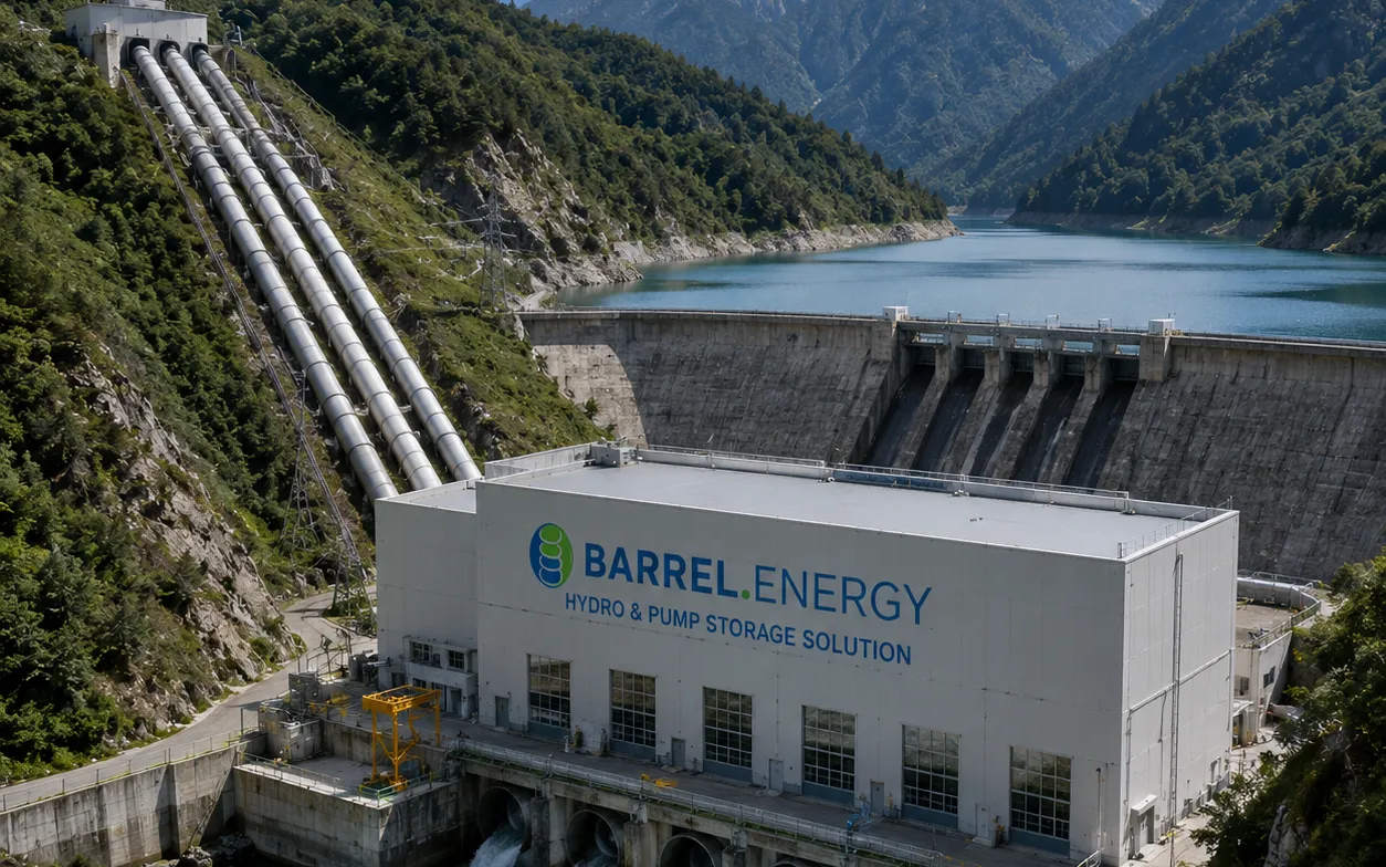
Pumped storage stores electricity as water held high in a reservoir and returns it to the grid when it is needed. BARREL treats it not as one more hydro plant but as integrated infrastructure — long-duration storage, reversible generation, hydraulic machinery, dams and underground works, high-voltage evacuation, renewable integration, EPC and decades of asset management.
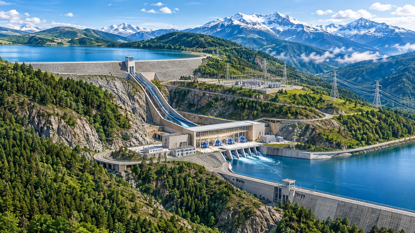
- Operating modes — pump and generate
- 2
- Indicative round-trip efficiency
- ≈ 70–85 %
- Typical storage duration
- 4–10 h+
- Plant types engineered
- 7
- BARREL delivery models
- 7
Section 01
Pumped storage hydropower — long-duration storage for the grid
Pumped Storage Hydropower (PSH) stores electrical energy as the gravitational potential energy of water. It moves water between two reservoirs at different elevations: in surplus hours it pumps water up; when the grid needs power it releases the water through reversible turbine-generators and sends the electricity out through transformers and the switchyard.
Unlike a conventional hydro plant, which generates from natural inflow, a pumped storage plant works in two modes — pumping mode, consuming electricity to store energy, and generation mode, releasing it. That makes it one of the most established technologies for utility-scale, long-duration storage, and a key partner for solar and wind.
How BARREL positions pumped storage
An integrated infrastructure business, not a single technology.
- Large-scale energy storage infrastructure
- Reversible hydroelectric generation
- Pumping and hydraulic machinery
- Dam, reservoir and underground civil engineering
- High-voltage transmission and grid infrastructure
- Renewable energy integration
- Energy trading and storage services
- Engineering, procurement and construction (EPC)
- Asset management, operation and maintenance
2Why pumped storage matters
Solar peaks at midday, demand peaks in the evening and wind follows the weather. System operators face:
- Renewable generation surplus during certain periods
- Renewable energy curtailment
- Evening and peak-hour electricity shortages
- Frequency and voltage fluctuations
- Rising need for flexible generation
- Transmission congestion
- Greater balancing and reserve requirements
- Growing demand for long-duration energy storage
The answer
Pumped storage shifts electricity from surplus hours to high-demand hours — and adds inertia, reserves and voltage support while it does so.
2.1Major strategic applications
- 01
Renewable energy storage
Stores surplus solar and wind electricity and returns it when renewable output falls.
- 02
Peak load management
Generates during peak demand, relieving conventional stations and the transmission network.
- 03
Grid frequency regulation
Active-power response and frequency support, subject to unit design and operating configuration.
- 04
Grid stability
Balancing, reserves, voltage control and system restoration where appropriately designed.
- 05
Renewable energy firming
Turns variable renewable generation into a more dispatchable supply.
- 06
Energy arbitrage
Pumps in low-price periods and generates in high-price periods — after round-trip losses and market rules.
- 07
Black start and restoration
Specially designed units can help restore the power system after a major outage.
- 08
Transmission optimisation
Well-located plants manage regional generation-demand imbalances and ease certain constraints.
Section 02
Technology and working principle
Two reservoirs at different elevations, connected by tunnels, shafts, penstocks, valves, surge facilities and a powerhouse. Water goes down to generate and up to store.
The two operating modes
Swipe sideways to see the full diagram. Conceptual cycle. In generating mode water falls through the pump-turbine; in pumping mode the motor-generator lifts it back.
3.1Pumping operation — surplus hours
- 1Electricity is received from the grid or an associated generating plant
- 2The motor-generator runs as an electric motor
- 3The reversible pump-turbine runs in pumping mode (or a separate pump in a separate-unit plant)
- 4Water is lifted from the lower reservoir to the upper reservoir
- 5The upper reservoir holds the water at a higher elevation
- 6The plant consumes electricity and increases its stored hydraulic energy
3.2Generation operation — peak demand
- 1Water is released from the upper reservoir
- 2It flows through the intake and the high-pressure waterways
- 3Hydraulic energy rotates the turbine
- 4The turbine drives the generator
- 5The generator produces electrical energy
- 6Power passes through generator transformers and the switchyard
- 7Electricity is supplied to the grid
- 8Water is discharged into the lower reservoir
3.3Energy conversion chain
- 1Electrical
- 2Mechanical
- 3Hydraulic potential
- 4Hydraulic kinetic
- 5Mechanical rotation
- 6Electrical
Where the losses go
Electricity generated is always less than electricity used for pumping. Each conversion takes its share:
- Energy taken from the grid100
- Transformer and motor losses (pumping)GSU transformer, motor-generator as motor−2.5
- Pump hydraulic lossespump efficiency ≈ 92 %−7
- Waterway friction, pumpingtunnels, shafts, penstock, intakes−2.5
- Waterway friction, generatingsame path in reverse−2.5
- Turbine hydraulic lossesturbine efficiency ≈ 92–93 %−6.5
- Generator and transformer lossesgenerator, GSU transformer−2
- Auxiliary consumption and transientscooling, drainage, start-ups, mode changes−1.5
- Energy returned to the grid≈ 76
Loss sources
- Motor-generator losses
- Pump and turbine hydraulic losses
- Waterway friction
- Hydraulic transients
- Transformer losses
- Auxiliary power consumption
- Mechanical and electrical system losses
Section 03
Types of pumped storage plants
Classified by reservoir arrangement, water source, hydraulic configuration, powerhouse arrangement and operating technology.
4.1Closed-loop pumped storage
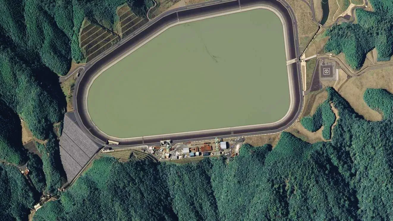
Two reservoirs not continuously connected to a naturally flowing river; both may be built for the project.
- Dedicated upper and lower reservoirs
- Controlled hydraulic circulation
- Limited dependence on continuous river inflow
- Potential flexibility in site selection
- Water needed mainly for first filling, evaporation, seepage and operating losses
- Potentially less direct interaction with river ecosystems than some open-loop schemes
Closed-loop projects still need detailed assessment of water availability, groundwater, biodiversity, land and environmental impacts.
4.2Open-loop pumped storage
A continuous hydraulic connection with a natural water body or an existing hydropower reservoir system.
- River-connected upper reservoir
- River-connected lower reservoir
- Existing dam reservoir as the upper reservoir
- Existing dam reservoir as the lower reservoir
- Integrated conventional hydro + pumped storage schemes
Can use existing water infrastructure, but needs careful evaluation of river hydrology, environmental flows, reservoir operations and downstream impacts.
4.3On-stream pumped storage
Uses existing or proposed reservoirs on a river system; may combine conventional hydropower and pumped storage.
- Builds on existing dams and reservoirs
- Shares water, civil works and grid connection
- Conventional and pumped generation in one scheme
4.4Off-stream pumped storage
Reservoirs located away from the main river channel — closed-loop or suitably configured open-loop.
- Away from the main river channel
- Lower flood and sediment exposure
- Often a short connection to a water source for filling
4.5Seawater pumped storage
The sea is one reservoir, with an elevated artificial reservoir on suitable coastal terrain.
- Saltwater corrosion protection
- Marine-grade materials
- Seawater-compatible pumps and turbines
- Intake and discharge structures
- Coastal erosion and marine ecology
- Waterproofing and lining systems
- Protection of groundwater from saltwater leakage
4.6Underground pumped storage
Underground caverns, mines, tunnels or excavated spaces form one or both reservoirs.
- Smaller surface land requirement
- Opportunity to repurpose suitable mining infrastructure
- Extensive investigation of containment, geology, pressure, groundwater and long-term structural safety
4.7Hybrid pumped storage
Pumped storage integrated with other energy resources as one renewable energy and storage complex.
- Solar photovoltaic and floating solar
- Onshore and offshore wind
- Conventional hydropower
- Battery energy storage systems
- Green hydrogen facilities
- Thermal and nuclear power plants
- Industrial captive power systems
Plant types side by side
| Type | Water source | River interaction | Main engineering focus |
|---|---|---|---|
| Closed-loop | First fill + make-up | Low (no continuous connection) | Two new reservoirs, lining, seepage |
| Open-loop | River or existing reservoir | Continuous | Hydrology, environmental flows, sediment |
| On-stream | River reservoir system | Direct | Dam operations, combined generation |
| Off-stream | Nearby source for filling | Limited | New reservoir away from the channel |
| Seawater | The sea | Marine | Corrosion, marine ecology, saltwater leakage |
| Underground | Mine water / first fill | Groundwater | Cavern stability, containment, pressure |
| Hybrid | As per base scheme | As per base scheme | Co-optimised dispatch with solar, wind, BESS |
Section 04
Plant configuration and technology
The hydraulic and electromechanical configuration follows the head, flow, storage requirement, operating flexibility and project economics.
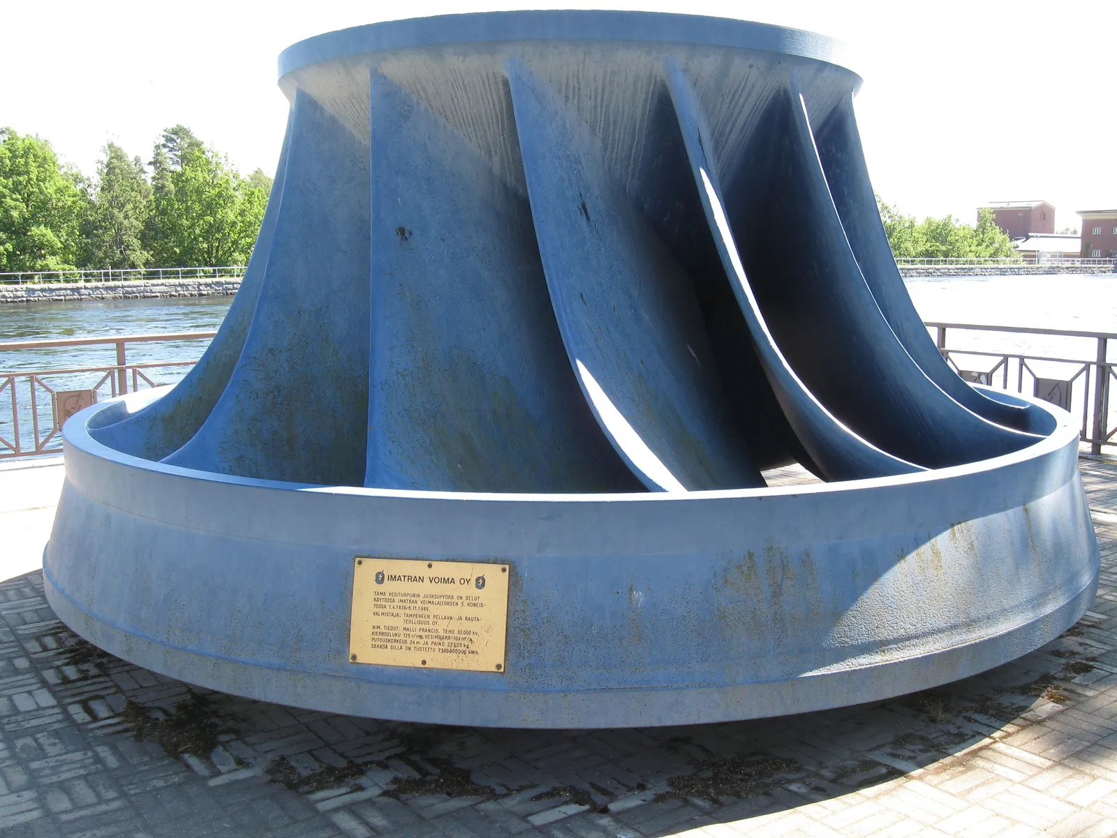
5.1Reversible pump-turbine
One machine pumps and generates, coupled to a motor-generator — the most common arrangement.
- Reversible Francis pump-turbines
- Fixed-speed reversible units
- Variable-speed reversible units
- Vertical-shaft arrangements
- Horizontal-shaft arrangements where suitable
5.2Separate pump and turbine
Pumping and generating by separate machines, each optimised independently.
- Independent optimisation of pump and turbine characteristics
- More equipment, installation space and capital cost
5.3Ternary unit
Separate pump and turbine on one shaft with a motor-generator, often with a hydraulic short-circuit.
- Separate hydraulic pump
- Separate hydraulic turbine
- Motor-generator
- Hydraulic short-circuit / bypass where provided
- Associated valves and control equipment
- Rapid transitions between operating states, depending on design
5.4Fixed-speed
Runs at a substantially fixed synchronous speed set by grid frequency and pole count.
- Conventional pumping and generating
- Simplest electrical arrangement
- Pumping power fixed by head
5.5Variable-speed
Controlled adjustment of pumping input and wider operating flexibility — doubly-fed or full-converter machines.
- Adjustable pumping power
- Wider operating range
- Better grid balancing capability
- Faster response to system conditions
- More flexibility under varying heads
Fixed-speed, variable-speed and ternary compared
| Feature | Fixed-speed | Variable-speed | Ternary |
|---|---|---|---|
| Pumping power control | Fixed by head | Adjustable | Adjustable with hydraulic short-circuit |
| Frequency support in pumping | Limited | Yes | Yes |
| Operating range under head variation | Narrower | Wider | Wide |
| Mode-change speed | Minutes | Faster | Fastest, depending on design |
| Electrical complexity | Lowest | Converter / doubly-fed machine | Moderate |
| Civil and machine space | Lowest | Similar to fixed | Largest (longer shaft line) |
Qualitative comparison; performance depends on the manufacturer, the machine and the grid code. Confirmed in the technical specification.
BARREL engineering principle
Choose the unit technology from the grid's needs — frequency support while pumping, head variation and mode-change time — not from the capital cost alone. Variable speed earns its premium only where those services are valued.
Section 05
Civil and hydraulic infrastructure
Reservoirs, intakes, tunnels, shafts and penstocks carry most of the cost and most of the risk. They are designed together from hydraulic, geological and transient studies.
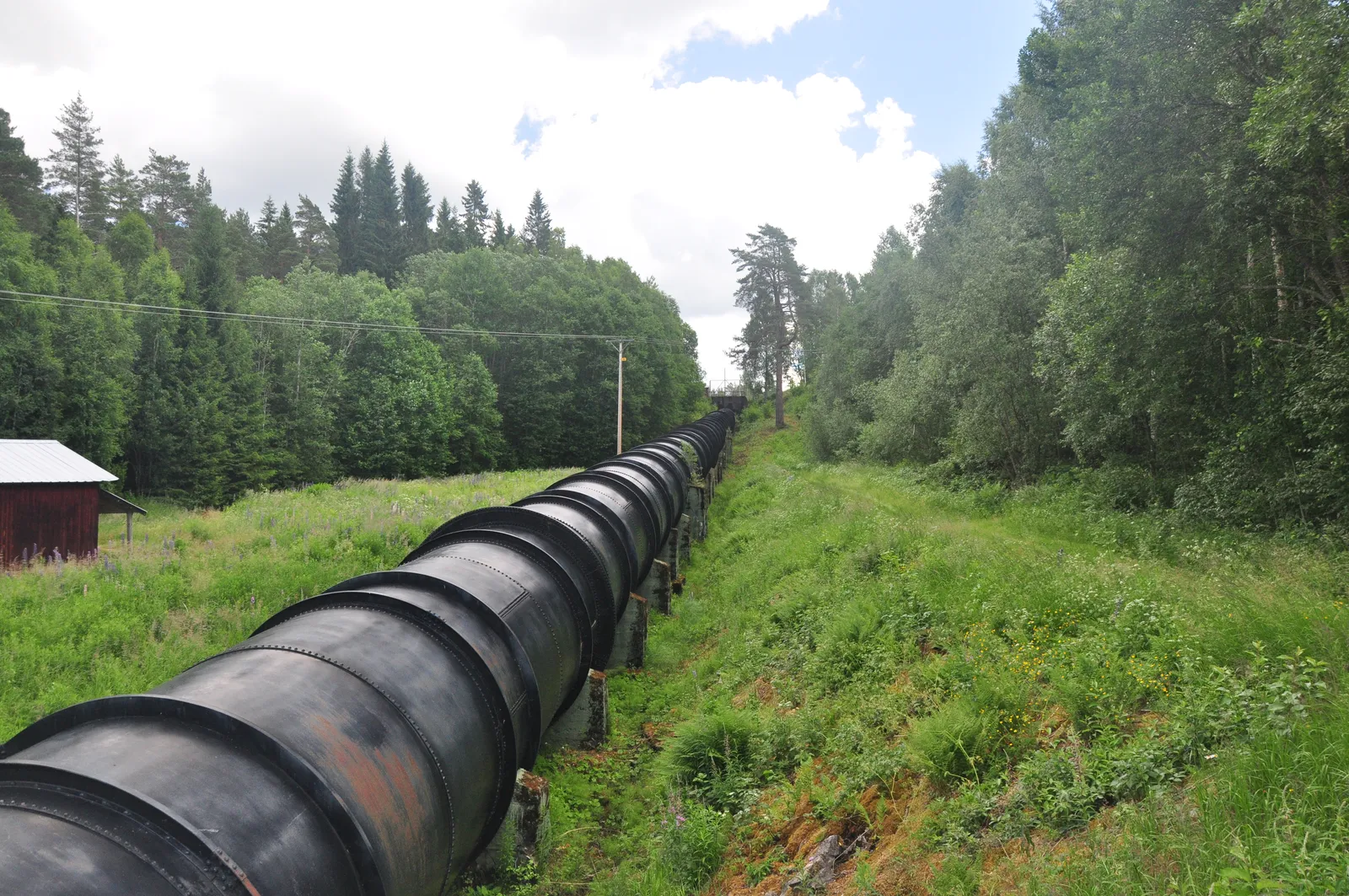
The scheme at a glance
Twelve parts from the upper reservoir to the grid; numbers match the cards below.
Swipe sideways to see the full diagram. Conceptual long-section of an underground-powerhouse scheme — not to scale, not a design drawing.
- 1Upper reservoir
- 2Intake / outlet
- 3Head race tunnel
- 4Upstream surge shaft
- 5Pressure shaft / penstock
- 6Main inlet valve
- 7Pump-turbine + motor-generator
- 8Draft tube
- 9Tail race tunnel
- 10Lower intake / outlet
- 11Lower reservoir
- 12GSU, switchyard, grid
6.1Upper reservoir
14- Reservoir basin
- Embankment or dam
- Upstream and downstream slopes
- Reservoir lining
- Waterproofing systems
- Intake structure
- Trash racks
- Stoplog arrangements
- Emergency overflow structures
- Spillway
- Outlet structures
- Level monitoring
- Seepage collection and drainage
- Instrumentation and monitoring
Sized from active storage, operating levels, dead storage, freeboard, evaporation, seepage and hydraulic operating conditions.
6.2Lower reservoir
10- Lower dam or embankment
- Reservoir basin
- Intake and outlet structures
- Trash racks
- Stoplogs
- Spillway and overflow structures
- Water-level measurement
- Sediment management
- Seepage control
- Reservoir instrumentation
6.3Intake structures
10- Intake tower
- Bell-mouth intake
- Trash racks
- Trash-rack cleaning
- Stoplog gates
- Emergency gates
- Intake valves
- Transition sections
- Anti-vortex arrangements
- Flow measurement
Designed to keep debris out, minimise hydraulic losses and work safely in both flow directions.
6.4Head race tunnel
12- Tunnel alignment
- Tunnel diameter
- Hydraulic losses
- Rock mass classification
- Excavation method
- Tunnel support
- Concrete lining
- Steel lining where required
- Waterproofing
- Drainage
- Construction access
- Geological fault zones
6.5Surge shaft and surge tank
6- Pressure surge management
- Water hammer mitigation
- Flow stabilisation
- Protection of waterways
- Safe unit start-up and shutdown
- Load rejection and mode transitions
Designed from hydraulic transient analysis, system geometry, operating scenarios and allowable pressure limits.
6.6Pressure shaft
5- Vertical, inclined or topography-led
- Unlined rock shafts where geotechnically feasible
- Concrete-lined shafts
- Steel-lined shafts
- Composite lining systems
6.7Penstock
12- Steel penstock pipes
- Branch pipes
- Bifurcations
- Expansion joints
- Anchor blocks
- Supports
- Inspection openings
- Access manholes
- Air admission
- Drainage and dewatering
- Pressure monitoring
- Protective coatings
Needs hydraulic, structural, fatigue, buckling, seismic and welding assessments.
6.12Draft tube and tail race
6- Draft tube
- Draft tube gates
- Tail race tunnel
- Tail race channel
- Outlet structures
- Energy dissipation arrangements
Discharges water to the lower reservoir in generation and forms the suction path in pumping.
Dams for pumped storage reservoirs
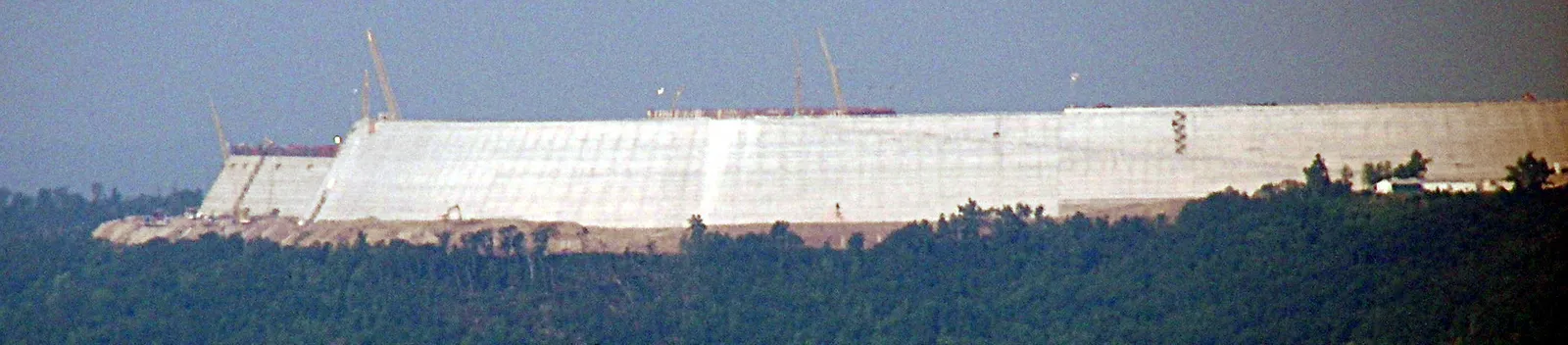
Upper reservoirs fill and empty every day. Lining, drainage, instrumentation and an overtopping-safe level control are design essentials — the 2005 Taum Sauk failure was caused by overfilling.
Section 06
Mechanical and hydro-mechanical systems
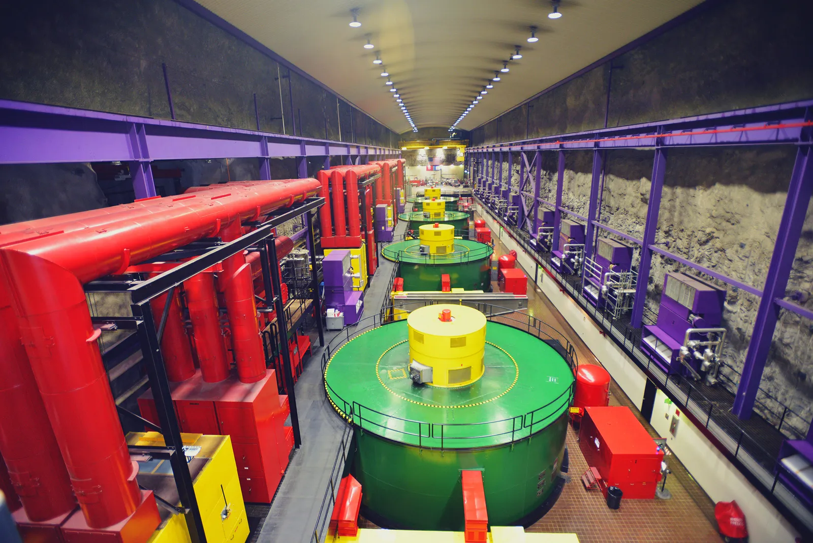
The powerhouse holds the machines that change direction every day — designed for frequent starts, mode changes and high head.
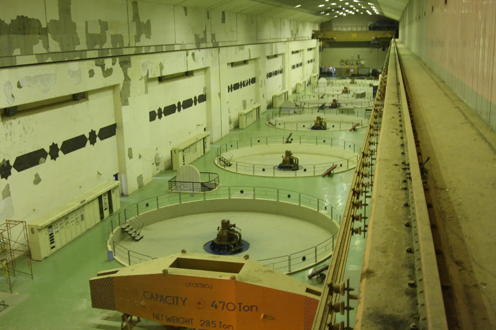
6.9Powerhouse
The powerhouse houses the principal electromechanical equipment.
Location options
- Underground rock cavern
- Surface
- Partially underground
- Near a dam or reservoir
- Purpose-built machine hall
Major facilities
- Machine hall
- Turbine-generator floor
- Service bay
- Erection bay
- Electrical galleries
- Cable galleries
- Ventilation system
- Fire protection
- Drainage and dewatering
- Maintenance workshop
- Control room
- Battery room
- Auxiliary equipment rooms
- Access tunnels and shafts
6.8Main inlet valve (MIV)
7- Spherical valves
- Butterfly valves
- Project-specific high-pressure isolation valves
- Hydraulic operating system
- Seals and bypass
- Position indicators
- Emergency closure
6.10Pump-turbine
10- Runner
- Spiral casing
- Stay vanes
- Guide vanes / wicket gates
- Shaft and shaft seals
- Bearings
- Draft tube
- Wear rings
- Hydraulic actuators
- Lubrication systems
6.11Motor-generator
9- Stator
- Rotor
- Excitation system
- Bearings
- Cooling systems
- Braking systems
- Shaft coupling
- Protection systems
- Electrical monitoring
Motor in pumping mode, generator in generating mode.
6.13Cranes and lifting
7- Overhead travelling cranes
- Gantry cranes
- Monorails
- Hoists
- Hydraulic lifting
- Maintenance lifting beams
- Special equipment handling
6.14Auxiliary systems
15- Cooling water
- Compressed air
- Drainage
- Dewatering
- Oil filtration
- Lubrication
- Hydraulic pressure units
- Ventilation
- Air conditioning
- Fire detection
- Fire suppression
- Water treatment
- Workshop facilities
- Emergency lighting
- Battery and DC systems
Underground machine hall
Section 07
Electrical systems and grid infrastructure
The electrical system must work safely in both directions — consuming power when pumping and supplying it when generating — and start large machines as motors.
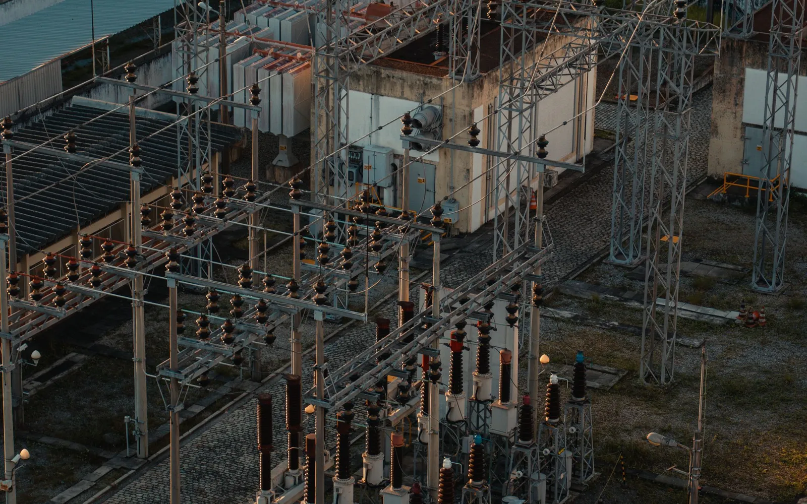
7.3Switchyard and substation
Voltage level is set by grid studies and connection approvals.
- 33 kV
- 66 kV
- 110 / 132 kV
- 220 kV
- 400 kV
- 765 kV
- GIS or AIS switchgear
- Circuit breakers
- Disconnectors
- Earthing switches
- CTs and CVTs
- Busbars
- Lightning arresters
- Wave traps where required
- Protection and control panels
- Metering
- Communication infrastructure
7.1Generator and motor electrical system
11- Motor-generator terminals
- Neutral grounding
- Generator circuit breaker
- Isolated phase bus / bus ducts
- Current transformers
- Voltage transformers
- Surge arresters
- Excitation system
- Protection relays
- Synchronising equipment
- Electrical metering
7.2Power transformers
6- Generator step-up transformers
- Unit auxiliary transformers
- Station service transformers
- Starting transformers
- Interconnecting transformers
- Spare transformers
7.4Transmission line
11- Route survey
- Tower spotting
- Foundation design
- Tower fabrication
- Tower erection
- Conductor stringing
- Earth wire and OPGW
- Insulators and hardware
- Testing and commissioning
- Line protection
- Grid connectivity
7.5Plant control and automation
13- Unit control systems
- Turbine governor
- Pump control
- Motor-generator control
- Excitation control
- Plant supervisory control
- SCADA
- DCS or PLC
- Protection and interlocking
- Reservoir monitoring
- Hydraulic monitoring
- Remote operation
- Energy management interfaces
7.6Communication and cybersecurity
11- Fibre optic communication
- OPGW
- Industrial Ethernet
- Redundant networks
- IEC 61850 substation communication
- Control centre connectivity
- Remote telemetry
- Secure engineering access
- Network segmentation
- Security event monitoring
- Backup and recovery
Starting a unit in pump mode
A pump-turbine cannot start itself as a pump: it is brought up to synchronous speed first, usually with the runner dewatered.
| Pump-mode starting method | How it works | Typical use |
|---|---|---|
| Static frequency converter (SFC) | Power electronics run the machine up to synchronous speed with the runner dewatered | Most large fixed-speed plants |
| Back-to-back start | One unit runs as generator and drives another as a motor | Back-up to the SFC, multi-unit plants |
| Pony motor | A small motor on the shaft line spins the unit up | Older or smaller plants |
| Hydraulic start (ternary) | The coupled turbine brings the pump up to speed | Ternary units |
| Converter-fed (variable-speed) | The machine's own converter controls speed from standstill | Variable-speed units |
Section 08
Engineering design parameters and calculations
Integrated hydraulic, geological, civil, mechanical and electrical studies fix the design. The physics fits on one line; the engineering does not.

8Principal design parameters
- Installed generating capacity (MW)
- Pumping capacity (MW)
- Number of units
- Unit capacity (MW)
- Gross head (m)
- Net head (m)
- Pumping head (m)
- Design discharge (m³/s)
- Upper reservoir storage (MCM)
- Lower reservoir storage (MCM)
- Active storage volume
- Operating reservoir levels
- Effective storage duration (h)
- Hydraulic efficiency
- Pump efficiency
- Turbine efficiency
- Motor-generator efficiency
- Round-trip efficiency
- Waterway diameter and length
- Pressure surge limits
- Machine rotational speed
- Grid voltage
- Power factor and reactive capability
- Start-up and transition times
- Availability and planned maintenance
8.1–8.4Core formulas
8.1 Hydraulic power
P = ρ × g × Q × H
Electrical output, generating
P = ρ × g × Q × H × η
8.2 Stored energy
E (MWh) = ρ × g × V × H ÷ (3.6 × 10⁹)
8.3 Storage duration
hours = deliverable MWh ÷ rated MW
8.4 Round-trip efficiency
RTE % = energy generated ÷ energy for pumping × 100
| Symbol | Meaning | Unit |
|---|---|---|
| P | Power | W (÷ 10⁶ for MW) |
| ρ | Water density (≈ 1,000 fresh, ≈ 1,025 sea) | kg/m³ |
| g | Gravitational acceleration ≈ 9.81 | m/s² |
| Q | Discharge | m³/s |
| H | Net head (generating) or pumping head | m |
| V | Usable (active) water volume | m³ |
| η | Overall efficiency at the operating point | — |
A rule of thumb: 1 million m³ falling 100 m holds about 272 MWh before losses. Head is the strongest lever on reservoir size.
8.5Worked example — 1,000 MW, 6-hour plant
Assumptions
- Installed generating capacity 1,000 MW (4 × 250 MW)
- Storage duration 6 hours at full output
- Gross head 500 m; waterway loss 3 % → net head 485 m generating, 515 m pumping
- Generating efficiency (turbine × generator × transformer) 88 %
- Pumping efficiency (pump × motor × transformer) 90 %
- Auxiliaries 1 % of pumping energy; pumping input 1,080 MW
Discharge, generating
Q = 10⁹ ÷ (9,810 × 485 × 0.88) ≈ 238.8 m³/s
Active volume
V = 238.8 × 6 × 3,600 ≈ 5.16 million m³
Pumping energy
9,810 × 5.16×10⁶ × 515 ÷ 0.90 ÷ 3.6×10⁹ × 1.01 ≈ 8,125 MWh
Round-trip efficiency
6,000 ÷ 8,125 ≈ 73.8 %
6,000 MWh
Delivered per cycle
≈ 5.16 MCM
Active water volume
≈ 8,125 MWh
Taken for pumping
≈ 7.5 h
To refill at 1,080 MW
An initial sizing illustration only. Head varies as reservoirs draw down, efficiencies vary with the operating point, and dead storage and freeboard add to the reservoir volume — all fixed in the feasibility study and DPR.
Pumped storage estimator
Change any value. Presets fill in typical assumptions; the first preset reproduces the worked example.
Indicative sizing
- Active storage volume
- 5.16 MCM
- million m³ of usable water · ≈ 1,163 MWh per MCM
- Deliverable energy
- 6,000 MWh
- Pumping energy
- 8,125 MWh
- Round-trip efficiency
- 73.8 %
- Net head (gen / pump)
- 485 / 515 m
- Discharge, generating
- 238.8 m³/s
- Discharge, pumping
- 192.4 m³/s
- Hours to refill
- 7.5 h
- Energy delivered / year
- 1,800 GWh
Q = P ÷ (ρ g Hn ηg); V = Q × hours × 3,600; pumping energy = ρ g V Hp ÷ ηp × (1 + aux). A screening estimate for comparing sites and options — not a feasibility study, DPR or equipment guarantee.
Section 09
Project site selection and feasibility
Site selection decides viability. A good site satisfies topography, geology, hydrology, environment, grid and commercial needs at the same time.

Screening indicators
How candidate sites are ranked before money is spent on drilling.
| Indicator | What it tells you | Favourable direction |
|---|---|---|
| Gross head | Energy per m³ of water | Higher head → smaller reservoirs and waterways |
| L / H ratio | Waterway length ÷ head — cost and transient behaviour | Lower; often below ≈ 10 is attractive |
| Active volume per MWh | Reservoir size needed | Lower |
| Geology | Tunnelling, cavern and dam foundation risk | Competent rock, few major faults |
| Distance to grid | Evacuation cost and losses | Shorter, to strong substations |
| Land and forest | Approvals, R&R and schedule | Less forest and fewer households |
| Water for first fill and make-up | Long-term operability | Reliable source with allocation |
9.1Topographical studies
10- Digital elevation model
- Contour mapping
- Upper and lower reservoir identification
- Elevation difference
- Reservoir capacity
- Dam alignment
- Tunnel alignment
- Access road planning
- Powerhouse location
- Transmission route
9.2Geological and geotechnical studies
16- Geological mapping
- Rock mass classification
- Structural mapping
- Fault and shear zones
- Borehole drilling
- Core logging
- Rock quality designation (RQD)
- Laboratory testing
- In-situ testing
- Rock mechanics
- Seismic assessment
- Slope stability
- Foundation investigation
- Groundwater investigation
- Permeability testing
- Grouting requirements
9.3Hydrological studies
12- Catchment assessment
- Rainfall analysis
- Water availability
- Inflow estimation
- Evaporation
- Seepage
- Flood estimation
- Probable maximum flood where applicable
- Sedimentation
- Water balance
- Reservoir operation
- Water replenishment
9.4Environmental and social assessment
14- Environmental baseline
- Biodiversity
- Aquatic ecology
- Forest and wildlife
- Land acquisition
- Rehabilitation and resettlement
- Community consultation
- Water resource impact
- Groundwater impact
- Construction impact
- Noise and dust
- Waste management
- Climate resilience
- Environmental management plan
9.5Grid connectivity and power market studies
12- Connectivity feasibility
- Load flow
- Short circuit
- Transient stability
- Dynamic stability
- Frequency response
- Reactive power
- Harmonics
- Grid code compliance
- Transmission capacity
- Renewable integration
- Power market and tariff
BARREL engineering principle
Drill before you draw. Most pumped storage cost overruns start underground — invest early in boreholes, adits and in-situ tests along the waterway and at the cavern.
Section 10
Complete project development lifecycle
Ten stages from the first map study to decades of operation. Each closes with documents the next stage depends on.
- Stage 01
Opportunity identification
- Potential locations
- Developers and investors
- Renewable integration opportunities
- Regional grid requirements
- Possible reservoir combinations
- Stage 02
Preliminary feasibility
- Topographical assessment
- Preliminary hydrology
- Geological reconnaissance
- Head and storage estimate
- Initial capacity
- Preliminary cost
- Initial financial evaluation
- Stage 03
Pre-feasibility and DPR
- Detailed topographical survey
- Geological investigations
- Geotechnical studies
- Hydrological studies
- Hydraulic design
- Civil design
- Electromechanical selection
- Grid studies
- Environmental and social assessment
- Cost estimate
- Implementation schedule
- Financial and economic analysis
- Detailed Project Report
- Stage 04
Approvals and development
- Land acquisition and rights
- Water allocation and permissions
- Environmental clearance
- Forest clearance
- Wildlife approvals
- CEA examination and concurrence
- Grid connectivity approvals
- Transmission approvals
- Construction permissions
- Financing and contracts
- Stage 05
Basic and detailed engineering
- General arrangement drawings
- Hydraulic calculations
- Dam and reservoir design
- Tunnel design
- Penstock design
- Powerhouse design
- Turbine and generator engineering
- Transformer and switchyard engineering
- Control and protection design
- Single-line diagrams
- Cable schedules
- Civil and structural drawings
- Equipment specifications
- Bill of quantities
- Stage 06
Procurement and manufacturing
- Technical specifications
- Vendor qualification
- Tendering
- Technical bid evaluation
- Commercial bid evaluation
- Purchase orders
- Design approval
- Manufacturing
- Factory acceptance testing
- Inspection
- Packing and dispatch
- Logistics
- Stage 07
Construction and installation
- Site mobilisation
- Access roads
- Reservoir development
- Dam construction
- Tunnel excavation
- Shaft excavation
- Powerhouse excavation
- Concrete works
- Penstock fabrication and installation
- Hydraulic machinery installation
- Generator installation
- Transformer installation
- Switchyard
- Transmission line
- SCADA and automation
- Stage 08
Testing and commissioning
- Civil completion inspections
- Hydraulic testing
- Penstock pressure testing
- Insulation testing
- Mechanical testing
- Protection testing
- Control and automation testing
- Synchronisation
- Pump-mode testing
- Generation-mode testing
- Performance testing
- Reliability testing
- Grid compliance verification
- Commercial operation readiness
- Stage 09
Commercial operation
- Performance acceptance
- Operational handover
- Final documentation
- Spares handover
- Training
- O&M mobilisation
- Warranty management
- Asset registration
- Commercial operation declaration
- Stage 10
Long-term O&M
- Preventive maintenance
- Predictive maintenance
- Condition monitoring
- Turbine and pump inspection
- Generator maintenance
- Transformer maintenance
- Dam safety monitoring
- Reservoir inspection
- Tunnel and penstock inspection
- SCADA maintenance
- Protection testing
- Efficiency optimisation
- Life extension
See also BARREL's nine-thread project lifecycle used across all power projects.
Section 11
Turnkey EPC solutions for pumped storage
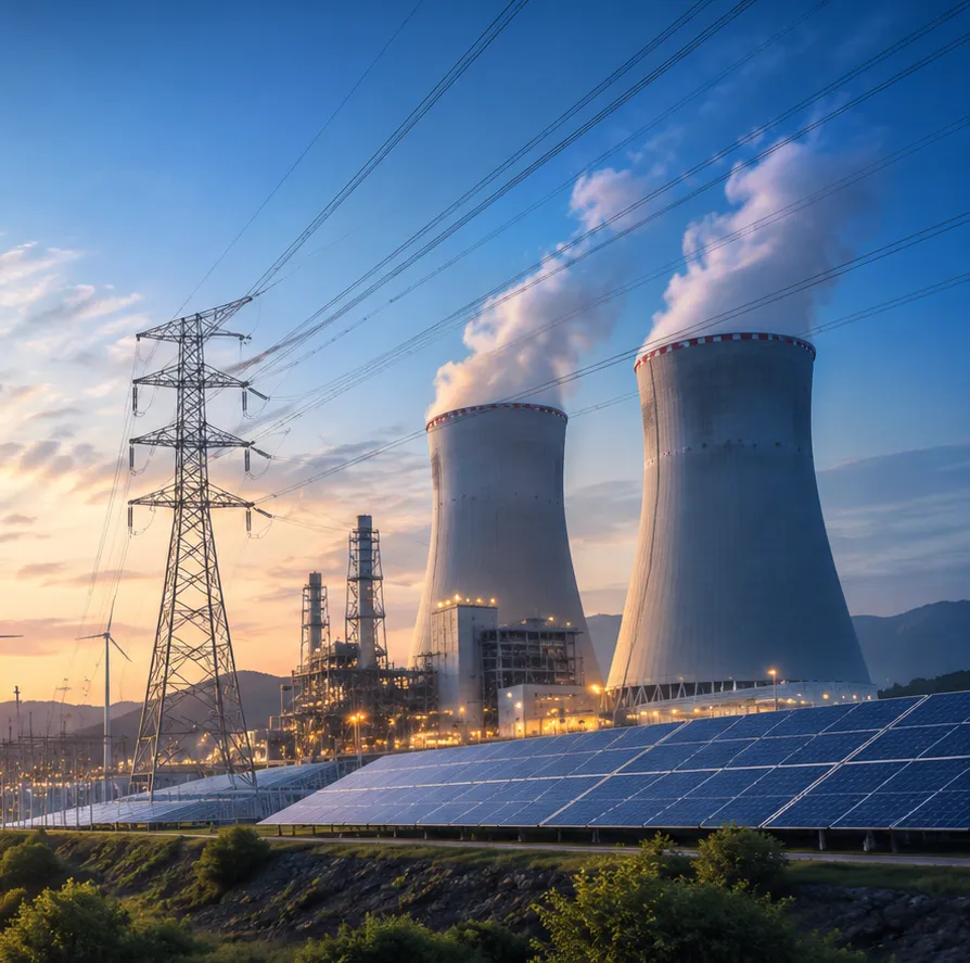
Turnkey delivery is structured to the owner's requirements and the contracting model — one complete package or several discipline packages.
11.1Complete turnkey EPC
15- Project engineering
- Civil construction
- Reservoir and dam infrastructure
- Waterways and hydraulic systems
- Powerhouse construction
- Pump-turbine equipment
- Motor-generators
- Electrical balance of plant
- Transformers
- Switchyard
- Transmission connectivity
- Automation and SCADA
- Testing and commissioning
- Performance guarantees
- Operational handover
Scope, interfaces, exclusions, risk allocation and performance obligations are defined in the EPC contract.
11.2Civil works EPC
15- Upper reservoir
- Lower reservoir
- Dam and embankment works
- Spillways
- Intake structures
- Head race tunnels
- Tail race tunnels
- Surge shafts
- Pressure shafts
- Penstocks
- Underground powerhouse caverns
- Access tunnels
- Roads and bridges
- Drainage
- Concrete and structural works
11.3Hydro-mechanical EPC
14- Intake gates
- Stoplogs
- Trash racks
- Trash-rack cleaning
- Emergency gates
- Main inlet valves
- Penstock components
- Embedded parts
- Hoists
- Hydraulic actuators
- Spillway gates
- Radial gates
- Maintenance gates
- Trash handling
11.4Electro-mechanical EPC
13- Reversible pump-turbines
- Separate pumps and turbines
- Motor-generators
- Excitation systems
- Governors
- Main inlet valves
- Bearings
- Cooling systems
- Lubrication systems
- Hydraulic power units
- Draft tube gates
- Auxiliary equipment
- Powerhouse cranes
11.5Electrical EPC
15- Generator electrical systems
- Generator transformers
- Auxiliary transformers
- Switchgear
- GIS and AIS substations
- Busbars
- Circuit breakers
- Protection panels
- Control panels
- AC and DC systems
- Batteries and chargers
- Earthing and lightning protection
- Cable trays and cabling
- Lighting
- Fire detection and suppression
11.6Transmission and grid EPC
13- Grid connection studies
- Line engineering
- Tower foundations
- Tower fabrication
- Tower erection
- Conductor stringing
- OPGW
- Substation extension
- Bay construction
- Grid protection
- Metering
- Communication
- Testing and commissioning
11.7Automation and digital EPC
12- Plant SCADA
- Unit control systems
- PLC and DCS
- Governor automation
- Excitation control
- Plant energy management
- Reservoir monitoring
- Dam safety instrumentation
- Remote monitoring
- Cybersecurity architecture
- Predictive maintenance
- Digital asset management
Where the money goes
Civil works usually dominate pumped storage capital cost.
- Civil works (reservoirs, dams, tunnels, caverns)40–60 %
- Electro-mechanical (units, MIV, auxiliaries)15–30 %
- Hydro-mechanical (gates, penstock steel)4–10 %
- Electrical, switchyard and evacuation5–12 %
- Land, R&R, environment2–10 %
- Engineering, management, IDC, contingency10–20 %
Section 12
Major equipment and procurement categories
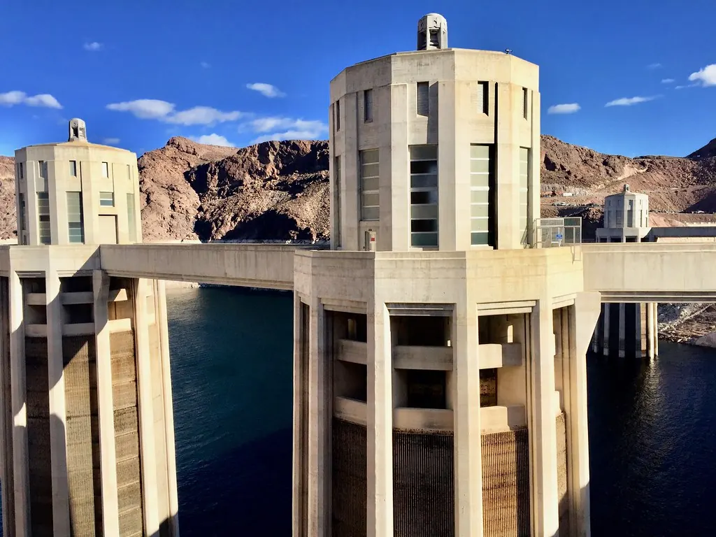
A pumped storage project buys from several specialised industries — heavy hydraulic machinery, large electrical machines, HV equipment, steel and civil materials, controls.
AHydraulic machinery
9- Reversible pump-turbines
- Francis turbines
- Centrifugal pumps
- Pump-turbine runners
- Guide vanes
- Main inlet valves
- Hydraulic actuators
- Shaft seals
- Bearings
BElectrical machinery
7- Synchronous motor-generators
- Variable-speed machines
- Static frequency converters
- Excitation systems
- Generator circuit breakers
- Generator transformers
- Auxiliary transformers
CHigh-voltage equipment
10- GIS
- AIS
- Circuit breakers
- Isolators
- Earthing switches
- CTs
- PTs and CVTs
- Surge arresters
- Busbars
- Protection relays
DCivil and structural materials
10- Cement
- Reinforcement steel
- Structural steel
- Penstock steel plates
- Concrete additives
- Waterproofing membranes
- Tunnel support systems
- Rock bolts
- Anchors
- Grouting materials
EHydro-mechanical equipment
8- Gates
- Hoists
- Trash racks
- Stoplogs
- Valves
- Embedded steel components
- Penstock fittings
- Expansion joints
FControl and instrumentation
11- PLCs
- SCADA servers
- RTUs
- Sensors
- Pressure transmitters
- Flow meters
- Level sensors
- Vibration monitoring
- Temperature monitoring
- Dam instrumentation
- Communication systems
BARREL engineering principle
Long-lead items — pump-turbines, motor-generators, SFCs, GSU transformers and MIVs — are ordered early and inspected at every stage. The model test of the runner comes before the prototype, never after.
Section 13
Testing and commissioning
From a scaled runner in a laboratory to a reliability run on the grid — every stage proves part of the guarantee.
- 01
Model tests
Scaled runner tested in a laboratory before the prototype is made.
- Efficiency hill chart, pump and turbine
- Cavitation limits
- Pump-mode stability (no positive slope)
- S-shape characteristic in turbine mode
- Pressure pulsations
- Acceptance per IEC 60193
- 02
Factory tests
Each major item tested at the works before dispatch.
- Runner and casing material, NDT
- Generator stator and rotor tests
- Transformer routine and type tests
- MIV leakage and operating tests
- Governor and excitation simulation
- Factory acceptance tests (FAT)
- 03
Site pre-commissioning
Systems checked dry, before water is admitted.
- Civil completion inspections
- Penstock and waterway pressure / filling tests
- Insulation and high-voltage tests
- Protection relay injection
- Control loop and interlock checks
- Auxiliaries and fire systems
- 04
Wet commissioning
Units run with water in both modes.
- First rotation and bearing run
- Synchronisation
- Generation-mode load tests and load rejection
- Pump-mode start (SFC / back-to-back) and pumping
- Mode-change sequences
- Transient pressure measurements
- 05
Performance and reliability
The plant proves its guarantees and grid compliance.
- Field efficiency tests per IEC 60041
- Output, pumping input and round-trip efficiency
- Reliability run
- Grid code compliance verification
- Commercial operation readiness
Acceptance is earned, not declared
Section 14
Operation and maintenance
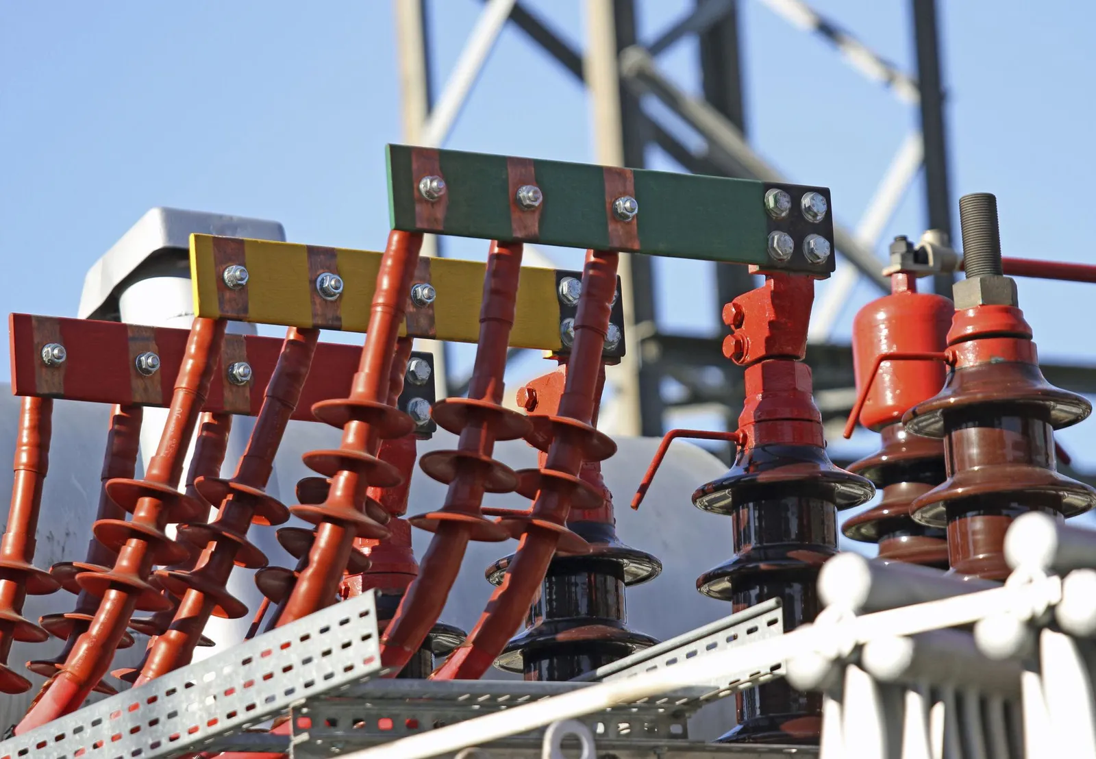
Pumped storage assets last for many decades. Long-term performance depends on systematic maintenance, monitoring and asset management.
16.1Reservoir and dam
8- Dam inspection
- Seepage monitoring
- Settlement monitoring
- Slope stability
- Spillway inspection
- Gate maintenance
- Water-level monitoring
- Sediment management
16.2Hydraulic system
7- Tunnel inspection
- Penstock inspection
- Valve maintenance
- Leakage monitoring
- Transient monitoring
- Corrosion protection
- Weld inspection
16.3Turbine and pump
8- Runner inspection
- Guide vane maintenance
- Bearing inspection
- Shaft alignment
- Seal replacement
- Vibration analysis
- Cavitation assessment
- Efficiency testing
16.4Electrical
7- Generator inspection
- Transformer testing
- Breaker maintenance
- Relay testing
- Insulation testing
- Earthing inspection
- Battery and charger maintenance
16.5Digital and control
7- SCADA maintenance
- PLC and control updates
- Cybersecurity monitoring
- Communication redundancy
- Alarm analysis
- Data backup
- Software lifecycle management
What we measure
- 01
Availability
Hours the units can pump or generate ÷ period hours.
- 02
Round-trip efficiency
Energy delivered ÷ energy consumed, measured per cycle and per year.
- 03
Starting reliability
Successful starts ÷ start attempts, per mode.
- 04
Mode-change time
Seconds or minutes from pump to generate and back.
- 05
Forced outage rate
Unplanned outage hours ÷ service plus outage hours.
- 06
Dam safety indicators
Seepage, piezometric levels and settlement within design limits.
Section 15
Digital pumped storage and AI
A digital plant model connects civil, mechanical, electrical and operating information in one asset data architecture — and turns it into schedules, alarms and decisions.

17Digital capabilities
- Digital twin of the whole plant
- 3D BIM models
- GIS-based asset mapping
- Hydraulic simulation
- Reservoir digital monitoring
- Dam safety analytics
- Turbine condition monitoring
- Predictive maintenance
- AI-assisted fault diagnostics
- Automated operating schedules
- Renewable generation forecasting
- Electricity price forecasting
- Energy optimisation
- Remote equipment monitoring
- Cybersecurity monitoring
- Integrated asset management
23The future of pumped storage
- Variable-speed pump-turbines
- Advanced power electronics
- Higher-efficiency hydraulic machinery
- Underground pumped storage
- Closed-loop reservoir systems
- Repurposed mining infrastructure
- Renewable energy integration
- Hybrid storage projects
- Digital twins
- AI-based predictive maintenance
- Automated energy optimisation
- Grid-forming and grid-support capabilities
- Smart transmission and energy management
BARREL OS
BARREL OS and BARREL AI bring project records, drawings, procurement, site progress and O&M data for a pumped storage asset into one place.
Section 16
Environment, sustainability and risk
Pumped storage helps integrate renewables and cut curtailment — but it is major infrastructure and must be developed responsibly.
18Environmental and social considerations
- Land use
- Forest diversion
- Biodiversity
- Wildlife movement
- Aquatic ecology
- Water availability
- Groundwater impacts
- Reservoir seepage
- Sedimentation
- Construction traffic
- Noise and vibration
- Dust
- Construction waste
- Community displacement
- Rehabilitation and resettlement
- Cultural heritage
- Climate resilience
Closed-loop projects can reduce some river-related impacts, but they do not remove the need for environmental assessment.
19Risks and engineering challenges
Geological
5- Unfavourable rock conditions
- Fault zones
- Groundwater ingress
- Tunnel instability
- Cavern deformation
Hydraulic
6- Water hammer
- Pressure fluctuations
- Cavitation
- Hydraulic losses
- Leakage
- Reservoir instability
Civil
5- Dam foundation problems
- Slope failure
- Concrete quality
- Seepage
- Structural settlement
Electromechanical
5- Turbine vibration
- Generator insulation failure
- Bearing problems
- Pump performance deviations
- Control system failure
Grid
5- Insufficient evacuation capacity
- Grid instability
- Protection coordination
- Harmonics
- Communication failures
Commercial
7- Construction cost escalation
- Project delays
- Financing cost
- Uncertain energy spreads
- Pumping electricity cost
- Lower-than-expected availability
- Performance disputes
BARREL engineering principle
Keep a live risk register from the first study — with quantitative risk assessment and a mitigation owner for every item — through to the end of the defects liability period.
Section 17
Project costing, finance and commercial models
Viability depends on the site, storage duration, capacity, civil works, hydraulic equipment, transmission, land, financing and the regulatory arrangement.

Capital expenditure
18- Land acquisition and site development
- Survey and investigation
- Upper reservoir
- Lower reservoir
- Dam and embankment works
- Tunnel and shaft excavation
- Penstock and hydraulic systems
- Underground powerhouse
- Pump-turbine equipment
- Motor-generators
- Transformers and switchyard
- Transmission and evacuation
- Control and automation
- Environmental mitigation
- Construction infrastructure
- Engineering and project management
- Interest during construction
- Contingencies and escalation
Operating expenditure
9- Personnel
- Maintenance
- Electricity for pumping
- Auxiliary electricity
- Water replenishment
- Insurance
- Dam safety monitoring
- Equipment replacement
- Administrative and regulatory
The model must account for
8- Round-trip losses
- Pumping electricity cost
- Availability
- Cycle limits
- Market rules
- Tariff structures
- Transmission charges
- Financing obligations
Revenue and commercial models
- Capacity-based storage contracts
- Fixed storage availability payments
- Pumped storage service agreements
- Energy arbitrage
- Peak power supply agreements
- Renewable firming agreements
- Renewable-plus-storage PPAs
- Ancillary service revenues
- Balancing and reserve services
- Merchant market participation where permitted
- Captive and group-captive storage where legally structured
- Long-term infrastructure concessions
The arbitrage test
Energy arbitrage pays only when the price spread beats the round-trip loss.
Break-even spread
sell price × RTE ≥ buy price → at 75 % RTE, ₹ 3.00 bought needs ≥ ₹ 4.00 sold per kWh
That is why most pumped storage projects rely on capacity, availability or storage-service payments rather than arbitrage alone.
Section 18
International standards and the India framework
Engineering follows national regulations, contractual specifications and internationally recognised standards. Editions, amendments and national adoptions are confirmed during design and tender.

13Technical references
- IEC 60041Hydraulic machinesField acceptance tests — hydraulic performance of turbines, storage pumps and pump-turbines
- IEC 60193Hydraulic machinesModel acceptance tests of hydraulic turbines, storage pumps and pump-turbines
- IEC 61362Hydraulic machinesGuide to specification of hydraulic turbine governing systems
- IEC 60034 seriesElectricalRotating electrical machines — motor-generators and variable-speed drives
- IEC 62271 seriesElectricalHigh-voltage switchgear and controlgear
- IEC 60076 seriesElectricalPower transformers
- IEC 60255 seriesElectricalMeasuring relays and protection equipment
- IEC 61850 seriesAutomationCommunication networks and systems for power utility automation
- ICOLD bulletinsCivil & damsDam design, safety, surveillance and emergency planning guidance
- Indian Standards (BIS)Civil & damsConcrete, steel, geotechnical, seismic and structural safety; hydraulic structures
- Dam Safety Act, 2021IndiaSurveillance, inspection, emergency action plans for specified dams in India
- CEA guidelinesIndiaFormulation and appraisal of pumped storage DPRs; technical standards for grid connectivity
Project and safety requirements
- Environmental and social safeguards
- Occupational health and safety
- Construction quality management
- Welding and NDT
- Fire and life safety
- Electrical safety
- Dam surveillance and emergency action planning
Listing a standard is not compliance
14India — regulatory and project development framework
The applicable framework depends on configuration, ownership, location, water source, land status and grid connection.
Authorities and regulatory interfaces
12- Ministry of Power
- Central Electricity Authority (CEA)
- Ministry of Environment, Forest and Climate Change
- Central Electricity Regulatory Commission
- State Electricity Regulatory Commissions
- State water resources departments
- State pollution control boards
- State transmission utilities
- Central and state transmission agencies
- Dam safety authorities
- Forest and wildlife authorities
- District and local development authorities
Project documentation
14- Pre-feasibility report
- Detailed Project Report
- Geological and geotechnical reports
- Hydrological report
- Hydraulic design report
- Environmental and social impact documentation
- Land and water documentation
- Grid connectivity studies
- Power evacuation plan
- Project cost estimate
- Financing plan
- Construction schedule
- Technical specifications
- Contractual documentation
CEA's published guidelines for formulation and appraisal of pumped storage DPRs are key references for Indian projects, together with the latest Ministry of Power and environmental requirements. Check current editions on the CEA website.
Section 19
BARREL pumped storage business solutions
One integrated platform for developers, utilities, IPPs, investors, infrastructure companies, industrial consumers, renewable developers and government agencies — across the whole value chain.
AProject development
9- Opportunity identification
- Site identification
- Preliminary feasibility
- Pre-feasibility studies
- DPR development coordination
- Project structuring
- Technical and commercial evaluation
- Investor and developer coordination
- Statutory approval coordination
BEngineering and consultancy
12- Civil engineering
- Dam engineering
- Reservoir engineering
- Geological and geotechnical
- Hydraulic engineering
- Mechanical engineering
- Electrical engineering
- Instrumentation and automation
- Transmission engineering
- Grid integration
- Cost engineering
- Project management
CManufacturing and supply chain
13- Hydraulic machinery
- Pump-turbine equipment
- Motor-generators
- Transformers
- Switchgear
- Substation equipment
- Penstocks
- Valves and gates
- Structural steel
- Electrical equipment
- Instrumentation
- Cables and conductors
- Industrial consumables
DProcurement and contracting
9- EPC contractor identification
- Global vendor sourcing
- Technical bid evaluation
- Commercial bid evaluation
- Tender management
- Procurement coordination
- Contract management
- Logistics coordination
- Inspection and QA
EConstruction and installation
9- Civil construction
- Dam and reservoir works
- Tunnelling
- Powerhouse construction
- Hydraulic equipment installation
- Electrical installation
- Substation construction
- Transmission line construction
- Testing and commissioning
FPower and energy integration
9- Solar integration
- Wind integration
- Renewable energy storage
- Battery integration
- Grid balancing
- Energy management
- Power evacuation
- Power trading coordination
- Storage capacity services
GOperation and maintenance
9- Plant operation
- Preventive maintenance
- Predictive maintenance
- Equipment inspection
- Testing and diagnostics
- Asset management
- Digital monitoring
- Life extension
- Spare parts management
21Turnkey project delivery models
- Model 1
Complete turnkey EPC
Single-point delivery of the agreed scope — engineering, procurement, construction, installation, testing and commissioning.
- Model 2
Balance of plant EPC
Civil, electrical, mechanical, hydraulic and auxiliary infrastructure packages.
- Model 3
Package-based EPC
Separate packages for reservoirs, tunnels, penstocks, powerhouse, electromechanical, switchyard and transmission.
- Model 4
Engineering & procurement management
Engineering, equipment selection, vendor management, tendering and procurement coordination.
- Model 5
Owner's engineer & PMC
Independent supervision, design review, QA, contract administration, construction monitoring, commissioning support.
- Model 6
Rehabilitation & modernisation
Upgrading existing hydroelectric infrastructure into pumped storage where technically and commercially feasible.
- Model 7
Renewable + storage integration
Integrated development of solar, wind, battery and pumped storage infrastructure.
What BARREL commits to is defined per project
22Why choose BARREL.ENERGY?
- Complete power-sector value chain coverage
- Multidisciplinary engineering coordination
- Global manufacturer and supplier ecosystem
- EPC and project execution coordination
- Technical and commercial procurement
- Grid and renewable energy integration
- Project finance and investment coordination
- Digital engineering and asset intelligence
- Operation and maintenance solutions
- Long-term infrastructure development
BARREL connects project owners, developers, consultants, manufacturers, suppliers, contractors, financial institutions, utilities and technology providers through one integrated power-sector ecosystem.
Section 20
Knowledge centre, FAQs and references
Short answers to the questions clients ask most, and the institutional sources behind this page.
FAQs
Q1What is pumped storage hydropower?
A large-scale storage plant that pumps water to an upper reservoir when electricity is surplus and releases it through turbines to generate when it is needed. It stores electricity as the gravitational potential energy of water.
Q2How is it different from a conventional hydro plant?
A conventional plant generates from natural inflow and head. A pumped storage plant also consumes electricity to pump, so it works in two modes — it is a storage asset as much as a generator.
Q3What round-trip efficiency should I expect?
An indicative planning range for many modern plants is about 70–85 %. The real figure depends on head, waterway losses, equipment, operating points and auxiliary consumption, and is confirmed by field tests.
Q4How many hours of storage does a plant have?
Storage duration = deliverable energy (MWh) ÷ rated capacity (MW). Many plants are designed for about 4–10 hours at full output; some reservoirs allow much longer.
Q5What is the difference between closed-loop and open-loop?
Closed-loop reservoirs are not continuously connected to a flowing river; open-loop schemes are connected to a river or an existing reservoir system. Both need full environmental and water assessment.
Q6Why does head matter so much?
Energy per cubic metre is proportional to head. Doubling the head halves the water volume and discharge needed for the same energy and power — smaller reservoirs, tunnels and machines.
Q7Fixed-speed or variable-speed?
Fixed-speed units pump at a power set by the head. Variable-speed units can adjust pumping power and support frequency while pumping, at the cost of converters or doubly-fed machines. The choice follows grid needs and head variation.
Q8How long does a project take?
Investigation, DPR and approvals often take several years; construction of a large plant commonly takes about 4–7 years depending on geology, size and access. Each project's schedule is built from its own studies.
Q9What water does a closed-loop plant consume?
Mainly the first fill, then make-up for evaporation and seepage. The volume depends on reservoir area, climate and lining, and is quantified in the water balance study.
Q10Can an existing dam be converted to pumped storage?
Sometimes — by adding a second reservoir, reversible units or a new pumping station to an existing reservoir. Feasibility depends on head, geology, water rights and the existing structures.
Q11How does pumped storage compare with batteries?
Batteries respond in milliseconds and suit shorter durations; pumped storage suits long durations, very large capacities and asset lives of many decades. Many grids will use both.
Q12Which studies does CEA expect for a DPR in India?
Topographical, geological, geotechnical, hydrological, hydraulic, electromechanical, power evacuation, environmental, cost and financial studies, following CEA's published guidelines for pumped storage DPRs. Check the latest edition.
Q13Can BARREL deliver a full turnkey plant?
BARREL coordinates development, engineering, procurement, construction and O&M through its platform and qualified partners. The actual contracted role, guarantees and statutory responsibilities are defined project by project.
Technical reference library
- CEA (India)Central Electricity Authority — hydro planning, pumped storage and DPR guidelines
- Ministry of PowerMinistry of Power, Government of India — hydro and pumped storage policy
- U.S. DOEWater Power Technologies Office — pumped storage hydropower
- IHAInternational Hydropower Association — pumped storage
- IFC / World BankGood Practice Note — environmental, health and safety approaches for hydropower projects
- JICAJapan International Cooperation Agency — hydropower development guidelines and manuals
- THDC IndiaTHDC India Ltd — Tehri pumped storage plant, 1,000 MW variable speed
- PNNLPacific Northwest National Laboratory — hydropower and pumped storage research
- ICOLDInternational Commission on Large Dams — technical bulletins
- IECIEC TC 4 — hydraulic turbines (IEC 60041, 60193, 61362)
Related BARREL pages
Partner with BARREL.ENERGY
From concept to commissioning.
Whether you are planning a new pumped storage plant, developing an existing hydro project, investing in long-duration storage, procuring hydro-mechanical equipment, building transmission or looking for an integrated EPC partner — BARREL supports you across the power and energy value chain. From energy storage to grid integration. From engineering to long-term asset management.
Connect with BARREL for
- Pumped storage project development
- Feasibility and DPR
- Turnkey EPC
- Pump-turbines and motor-generators
- Gates, valves and penstocks
- Switchyard and transmission
- Renewable + storage integration
- Investment and project finance
- Supplier and technology partnerships
BARREL.ENERGY · Rooted in Bharat. Global by Vision. One World. One Power Network.