
- Energy Storage
- Family 07
- Cold
- Load Shifting
- Cooling
Cold Energy Storage
Ice | Chilled Water | Phase-Change | Cryogenic | District Cooling | Data Centres | Cold Chain
Make the cold at night, use it in the afternoon.
Cooling is one of the largest and fastest-growing electricity loads in India, and it peaks in the hot afternoons and evenings when the grid is most stressed. Cold storage makes ice or chilled water when power is cheap or solar is plentiful, and releases the cooling during the peak. It cuts peak demand charges, lets chillers be smaller and gives critical sites a cooling reserve. BARREL can study, design, build and operate cold storage for buildings, campuses, district cooling, data centres, cold chain and industry, with equipment through OEM partners.
MMake
Ice or chilled water off-peak or on solar
KKeep
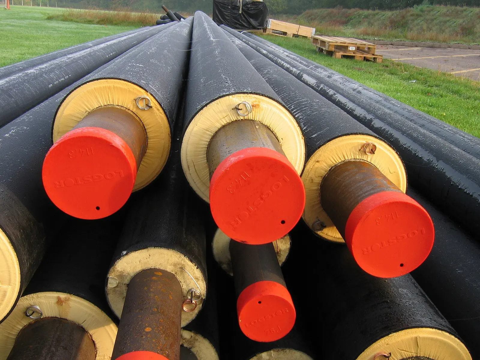
Insulated tanks, coils and capsules
RRelease
Cooling at the peak, chillers rest
- Typical daily shift
- 4–12 h
- Chiller peak cut
- 30–50 %
- Latent cold in ice
- ~85 kWh/m³
- Tank life
- 25–30 yrs
- Size range (thermal)
- kWh–GWh
Section 01
Cold Storage — Overview
Cold thermal energy storage keeps cooling capacity in water, ice, a phase-change material or a cryogenic liquid. Chillers run when power is cheap or solar is plentiful; the store supplies the building or process later.
It is not a battery: it stores cooling, not electricity. But because cooling is often the largest electric load on a site — 40–60 % of the bill in many Indian offices, malls and hospitals — shifting it has much the same effect on the bill and on the grid, usually at a lower cost per kWh shifted than batteries.
1.1Cold storage media at a glance
| Medium | How it stores cold | Store size for the same cooling | Best for |
|---|---|---|---|
| Chilled water | Sensible heat, water stored at about 4–6 °C in a stratified tank | Largest (≈ 8–12 kWh(th)/m³) | Campuses, district cooling, data centres, large industry |
| Ice | Latent heat of freezing at 0 °C | About ⅕ to ⅓ of chilled water | Buildings with limited space, low-temperature supply |
| Phase-change materials | Latent heat at a chosen temperature (−30 °C to +20 °C) | Small | Cold chain, cold rooms, retrofit, special temperatures |
| Cryogenic | Liquid air, nitrogen or LNG at −160 to −196 °C | Small, but very cold | LNG terminals, industry, liquid air energy storage |
1.2Why sites install cold storage
01
Lower bills
Run chillers on night or solar-hour tariffs and avoid the peak tariff and the maximum-demand charge.
02
Smaller chillers
In a new building the chiller plant can be sized for the average load, not the peak, saving capital.
03
Grid support
Shifts several MW of afternoon and evening load into the solar hours or the night, helping the DISCOM.
04
Cooling reserve
Hospitals and data centres keep minutes to hours of cooling if chillers or power fail.
05
Solar matching
Store midday solar as cold for the evening, raising rooftop and open-access solar use.
06
Longer life
Chillers run steadily at their best load instead of cycling; tanks last 25–30 years.
- Ice-on-coil
- Encapsulated ice
- Ice slurry
- Stratified chilled water
- Low-temperature fluid
- PCM
- LNG cold
- Liquid air
- District cooling
- Data centres
- Cold chain
Ice stores about 334 kJ/kg as latent heat — roughly 85 kWh of cooling per cubic metre of solid ice, or about 40–50 kWh per cubic metre of practical tank. Chilled water at an 8 K temperature difference holds about 9 kWh per cubic metre. All figures on this page are typical or indicative ranges from public literature, not project guarantees.
Section 02
How Cold Storage Works
Every cooling system moves heat out of a building or process and rejects it outside. A cold store simply puts a reservoir between the chiller and the load: the chiller fills the reservoir with cold when it suits the tariff, and the load draws from it when it needs cooling.
Cold can be stored as sensible heat (water gets colder, then warmer) or as latent heat (water freezes into ice, then melts). Latent storage packs far more cooling into the same volume, but the chiller has to work at a lower temperature to make it.
2.1Daily charge and discharge cycle
- Off-peak or solar hours
- Chiller runs at full, efficient load
- Store charges (water cools or ice forms)
- Peak hours
- Store discharges
- Chilled water to AHUs or process
- Chillers off or throttled
- Peak demand and bill cut
2.2Sensible versus latent storage
| Aspect | Sensible (chilled water) | Latent (ice / PCM) |
|---|---|---|
| What changes | Temperature of the water | State: liquid ↔ solid at a fixed temperature |
| Energy per kg | 4.19 kJ/kg per kelvin (≈ 33 kJ/kg at ΔT 8 K) | 334 kJ/kg for ice; 150–250 kJ/kg for most PCMs |
| Chiller leaving temperature | 4–6 °C (normal chiller) | −6 to −3 °C glycol for ice; matched to PCM melting point |
| Chiller efficiency while charging | Normal | Lower: capacity and COP fall by roughly 20–35 % for ice-making |
| Supply temperature on discharge | Same as charge, 4–6 °C | As low as 1–3 °C from ice — allows low-temperature air |
| Tank size | Large | Small |
2.3Key terms in plain words
Ton of refrigeration (TR)
3- 1 TR = 12,000 Btu/h
- 1 TR = 3.517 kW of cooling
- Indian HVAC uses TR everywhere
TR·h (ton-hour)
3- 1 TR for one hour
- 1 TR·h = 3.517 kWh(th)
- Storage size is quoted in TR·h
ΔT (delta-T)
3- Return minus supply water temperature
- Typical 5.5 K (old), 8–10 K (good design)
- Wider ΔT = smaller tank and pumps
COP / kW per TR
3- COP = cooling ÷ electricity
- Good water-cooled plant 0.6–0.8 kW/TR (chiller only)
- Whole plant incl. pumps and towers 0.8–1.2 kW/TR
Full / partial storage
3- Full: chillers off at peak
- Partial: chillers and store share the peak
- Choice set by tariff and space
Thermocline
3- The thin layer between cold and warm water
- Typically 0.3–1 m thick
- Kept sharp by slow, even flow
kW per TR and COP figures are indicative for Indian conditions (35–45 °C ambient); actual values depend on the chiller, condenser water temperature and part load.
Section 03
Ice-on-Coil Storage
The most common ice storage in buildings. Plastic or steel coils sit in a tank of water. During charging a glycol solution at about −6 to −3 °C flows through the coils and ice builds up on the outside of the tubes. During discharge the ice melts and chills the building's water loop.
Two variants exist. In internal melt, warm glycol flows back through the same coils and melts the ice from the inside — the tank water never leaves the tank. In external melt, the building's water circulates directly over the ice, giving very cold water and fast discharge.
3.1Internal melt versus external melt
| Feature | Internal melt | External melt |
|---|---|---|
| Fluid in contact with ice | Glycol inside the coil | System water over the ice |
| Typical supply temperature | 1–4 °C (glycol) | About 1–2 °C (water) |
| Discharge rate | Moderate, falls as ice melts | High, steady |
| Tank | Closed, modular, factory-built | Open, often site-built concrete |
| Ice build-up control | Simple; coil fully frozen | Thickness must be limited to keep water paths open |
| Typical use | Offices, malls, hospitals, hotels | District cooling, process, large plants |
| Water treatment | Tank water static | Tank water in circuit; treatment needed |
3.2What the system contains
Ice tanks
3- Modular polyethylene or steel tanks
- Or large concrete pits with coil bundles
- Insulated lid and walls
Glycol loop
3- 25–30 % ethylene or propylene glycol
- Glycol chillers rated for ice duty
- Plate heat exchanger to the water loop
Controls
3- Ice inventory sensor (level or conductivity)
- Charge / discharge valves
- Mode logic in the BMS
3.3Operating modes
- Ice-making (night)
- Ice-making plus direct cooling (night loads)
- Chiller only (mild days)
- Ice melt only (peak, chiller off)
- Chiller plus ice melt (design day)
Temperatures and glycol concentrations are typical values; the OEM's selection software sets the exact figures for each tank and load profile.
Section 04
Encapsulated Ice and Dynamic Ice Systems
Encapsulated systems fill thousands of plastic balls or flat containers with water (or a PCM), pack them into a steel or concrete tank and pass cold glycol around them. The water inside freezes; on discharge warmer glycol melts it. The tank can be any shape, so it fits basements and odd spaces.
Dynamic systems make ice and move it: ice harvesters freeze thin sheets on plates and drop them into a pit; ice-slurry machines make a pumpable mixture of tiny crystals in water. Both charge and discharge very fast.
4.1Types
01
StaticIce balls (nodules)
Plastic spheres, typically 75–100 mm, filled with water and a nucleating agent. Packed tank holds about 50–60 % water by volume. Simple, no moving parts.
02
StaticFlat containers and plates
Rectangular capsules stacked in racks; good flow distribution and easy inspection. Also used with PCMs at +5 to +10 °C.
03
DynamicIce harvester
Water flows over refrigerated plates; a thin ice sheet forms and is released by a brief hot-gas defrost into a storage pit. Water at about 1 °C is drawn off.
04
DynamicIce slurry
A scraped-surface or supercooling generator makes fine crystals; the slurry is pumped to storage or straight to the load. Very fast discharge.
05
StaticIce-on-pipe in pits
Large site-built pits with bare-pipe coils, used in district cooling and dairies (the classic Indian ice bank).
06
IndustryIce banks for dairies
Milk chillers have used ice banks for decades so small compressors can cool milk quickly at collection times.
4.2Choosing between ice systems
| System | Space needed | Discharge speed | Efficiency while charging | Complexity |
|---|---|---|---|---|
| Ice-on-coil, internal melt | Low | Medium | Medium | Low |
| Ice-on-coil, external melt | Low | High | Medium–low (thicker ice) | Medium |
| Encapsulated | Low–medium | Medium | Medium | Low |
| Ice harvester | Medium | Very high | Lower (defrost cycles) | High |
| Ice slurry | Medium | Very high | Medium | High |
Ball sizes, packing fractions and comparative ratings are indicative; they vary by product and should be confirmed from OEM data for each design.
Section 05
Stratified Chilled-Water Storage
A large insulated tank holds cold water (about 4–6 °C) at the bottom and warm return water (about 12–16 °C) at the top. Because cold water is denser, the two layers stay apart with a thin thermocline between them. Slow, even diffusers at top and bottom keep the layers from mixing as water is drawn and returned.
Chilled-water tanks are the cheapest cold store per kWh at large scale, use normal chillers at normal efficiency, and can double as a fire-water reserve. Their drawback is size — for the same cooling they need roughly three to five times the volume of an ice store.
5.1How much cooling a tank holds
Stored cooling
Q = V × ρ × cₚ × ΔT × FoM ÷ 3,600
5,000 m³ × 1.163 kWh/m³·K × 8 K × 0.9 ≈ 41.9 MWh(th) ≈ 11,900 TR·h
A wider temperature difference between supply and return stores more cooling in the same tank. The figure of merit allows for the thermocline and mixing that make part of the water unusable.
| Symbol | Meaning |
|---|---|
| V | Water volume (m³) |
| ρ × cₚ | ≈ 4,186 kJ/m³·K for water (= 1.163 kWh/m³·K) |
| ΔT | Return minus supply temperature (K) |
| FoM | Figure of merit, typically 0.85–0.95 for a well-designed tank |
| Q | Stored cooling (kWh thermal) |
5.2Design points that make a tank work
Geometry
3- Tall tanks stratify better; height 10–30 m is common
- Height-to-diameter ratio often 0.5–1.5 for large tanks
- Above ground (steel or concrete) or partly buried
Diffusers
3- Octagonal or radial pipe diffusers, or slotted plates
- Low inlet velocity so cold water spreads as a gravity current
- Design on inlet Froude number (≈ 1 or below) and Reynolds number
Temperatures
3- Supply 4–6 °C; water is densest near 4 °C
- Return as warm as the coils allow (12–16 °C)
- Low-temperature fluid additives allow supply near 1–2 °C
Extras
3- Tank can serve as fire-water storage (with approval)
- Also usable as a hot-water store in winter climates
- Sensors every 0.3–1 m up the tank wall to track the thermocline
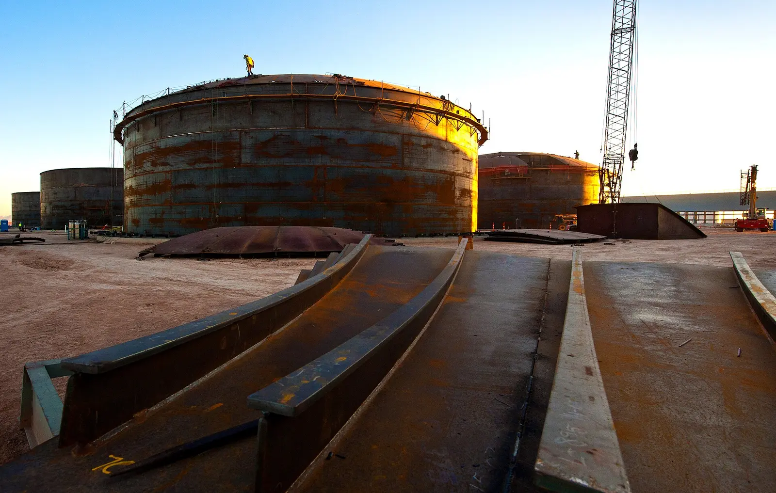
Temperatures, figure-of-merit values and tank proportions are typical ranges from ASHRAE guidance and published case studies; each tank needs its own diffuser and stratification design.
Section 06
Phase-Change Materials (PCM) for Cold Storage
A phase-change material melts and freezes at a chosen temperature, so cold can be held exactly where a product or process needs it — +8 °C for chilled water, +2 to +8 °C for vaccines, −18 to −25 °C for frozen food.
PCMs are packed in capsules, panels, plates or containers. They charge from a chiller, a refrigeration unit or solar-powered compressors, and hold temperature through power cuts — a strong advantage in rural Indian cold chains.
6.1PCM families
| Family | Typical melting range | Latent heat (indicative) | Notes |
|---|---|---|---|
| Water / ice | 0 °C | 334 kJ/kg | Cheapest, best known |
| Eutectic salt solutions | −50 to 0 °C | 150–300 kJ/kg | Frozen food, ice-cream, reefer plates; can be corrosive |
| Salt hydrates | +5 to +30 °C | 150–250 kJ/kg | High density; need stabilisers against separation |
| Paraffins | −10 to +30 °C | 150–250 kJ/kg | Stable, non-corrosive; flammable, lower density |
| Bio-based (fatty acids, esters) | −20 to +30 °C | 150–200 kJ/kg | Renewable feedstock; cost falling |
6.2Where PCMs are used
01
Cold rooms and pack houses
PCM panels in the walls or ceiling hold temperature through 6–12 h of power cuts; solar compressors charge them by day.
02
Vaccine and pharma
PCM packs in shippers and refrigerators keep +2 to +8 °C without power for days.
03
Reefer trucks and containers
Eutectic plates charged at the depot replace diesel-driven refrigeration on short routes.
04
Chilled-water plants
Encapsulated PCM at +5 to +10 °C works with normal chillers and stores more per m³ than water.
05
Data-centre racks
Small PCM buffers at rack or row level ride through short cooling outages.
06
Milk chilling
PCM or ice-bank chillers at village collection centres cool milk without a reliable grid.
6.3Points to check
- Supercooling: some PCMs freeze below their melting point; nucleating agents are needed.
- Phase separation in salt hydrates over many cycles.
- Low thermal conductivity: fins, thin plates or capsules are needed for fast charging.
- Flammability (paraffins) and corrosion (salts) — container material and fire rules.
- Cycle-life test data from the supplier (thousands of cycles).
- End-of-life take-back and disposal.
Melting ranges and latent heats are indicative ranges from published PCM literature; each product has its own data sheet.
Section 07
Cryogenic Cold — LNG Cold Recovery and Liquid Air
LNG arrives at import terminals at about −162 °C and must be warmed back to gas, normally by sea water or burners. That warming throws away a large amount of high-grade cold. Recovering it can run air-separation units, cold warehouses, data-centre cooling or even a small power cycle.
Liquid air (about −194 °C) and liquid nitrogen (−196 °C) can also be used as stores: liquid air energy storage makes liquid air with surplus power and later re-gasifies it to drive a turbine, reusing the stored cold to cut the next liquefaction's energy.
7.1Uses of cryogenic cold
LNG terminal cold
4- Air separation (oxygen, nitrogen)
- Cold warehouses and food freezing next to the terminal
- Power from a cold Rankine cycle
- Cooling for nearby data centres or industry
Liquid air / nitrogen
4- Liquid air energy storage (power-to-power)
- Cryogenic freezing of food and medicine
- Back-up cooling for critical sites
- Truck refrigeration with liquid nitrogen
Hydrogen and future fuels
3- Liquid hydrogen at −253 °C
- Boil-off and cold recovery at LH₂ terminals
- Cold reuse in hydrogen liquefiers
7.2Reference facts (indicative)
| Item | Value / fact |
|---|---|
| LNG temperature | About −162 °C at near-atmospheric pressure |
| Cold released warming LNG to ambient | About 800–900 kJ/kg (latent plus sensible); only a part is usefully recoverable |
| Liquid nitrogen boiling point | −196 °C |
| Liquid air energy storage round-trip | Roughly 50–70 % in studies, higher with waste heat or waste cold |
| Reference plant | A 5 MW / 15 MWh pre-commercial liquid air plant ran near Manchester, UK, from 2018 |
| LNG cold power | Japanese LNG receiving terminals have used LNG cold for power generation and air separation since the late 1970s |
| India LNG terminals | West coast: Dahej, Hazira, Dabhol, Kochi, Mundra; east coast: Ennore, Dhamra |
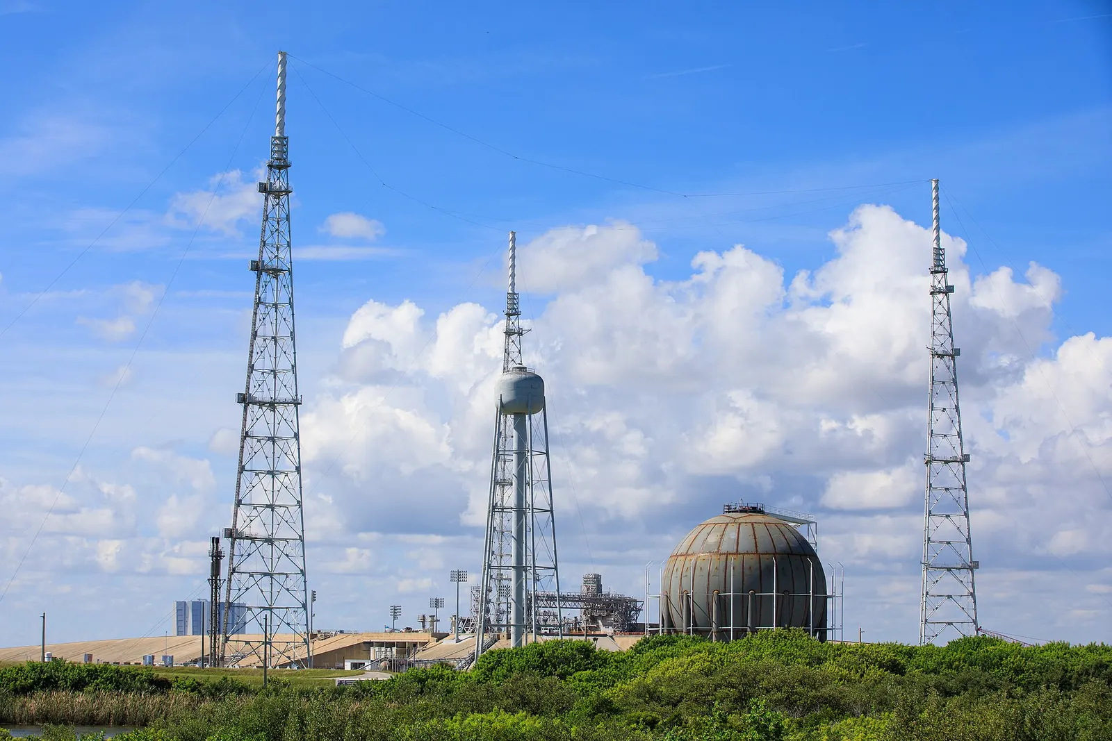
Cryogenic cold projects are site-specific and need PESO approvals for pressure vessels and gas handling. Efficiency and energy figures are indicative from public studies.
Section 08
System Types and Configurations
How much of the peak the store carries, and where it sits in the pipework relative to the chiller, decides tank size, chiller size and savings. The choice follows from the 24-hour load profile, the tariff and the space available.
8.1Operating strategies
| Strategy | What it means | Tank | Chiller | Best when |
|---|---|---|---|---|
| Full storage | Chillers off during the peak; the store carries all cooling | Largest | Sized to recharge in off-peak hours | Peak tariff is very high or demand charge dominates |
| Partial storage — load levelling | Chillers run all day at a steady rate; the store tops up the peak | Moderate | Smallest (≈ daily TR·h ÷ 24) | New building; capital saving on chillers matters |
| Partial storage — demand limiting | Chillers capped at a set kW during the peak | Moderate | Between the two | A target maximum demand or contract demand |
| Back-up / ride-through | Store kept full; used only when chillers or power fail | Small | Normal | Data centres, hospitals, pharma |
| Solar-matched | Charge during solar hours, discharge evening and night | Moderate | Sized for solar window | Large rooftop or open-access solar, ToD solar-hour tariff |
8.2Piping arrangements
Chiller upstream (series)
3- Chiller cools first, ice trims
- Chiller runs at warmer, more efficient temperature
- Common with ice-on-coil
Chiller downstream (series)
3- Ice cools first, chiller trims
- Uses ice fully; chiller at lower temperature
- Good for low-temperature supply
Parallel
3- Chiller and store each feed the load
- Typical for chilled-water tanks
- Tank acts as the decoupler
8.3By scale
01
Small
Cold rooms, shops, telecom: PCM or modular ice, 50–1,000 TR·h.
02
Building
Office, mall, hospital, hotel: ice-on-coil or encapsulated, 1,000–20,000 TR·h.
03
Campus / industry
Universities, pharma, auto plants: chilled-water tank, 10,000–60,000 TR·h.
04
District
Business districts, smart cities, airports: chilled-water or external-melt ice, 50,000 TR·h and above.
Size bands are indicative and overlap; the right medium is chosen by cost, space and supply temperature, not by scale alone.
Section 09
Technical Architecture and Components
A cold-storage plant is a chiller plant with an extra reservoir and a smarter control strategy. Most components are standard HVAC equipment made in India; the storage tank, diffusers or ice coils and the controls are where the design skill lies.
9.1Main components
Cooling production
4- Water-cooled screw or centrifugal chillers
- Glycol / ice-duty chillers (dual-duty)
- Air-cooled chillers for small sites
- Cooling towers and condenser pumps
Storage
4- Steel or concrete tank, or modular ice tanks
- Diffusers, ice coils or capsules
- Insulation and vapour barrier
- Level, temperature and inventory sensors
Distribution
4- Primary and secondary pumps with VFDs
- Plate heat exchangers (glycol to water)
- Motorised mode valves
- Air separators, expansion tanks, strainers
Loads
4- Air-handling units and fan-coil units
- Process heat exchangers
- Data-hall CRAH units
- Cold rooms and blast freezers
Water and glycol
3- Chemical dosing and side-stream filters
- Glycol make-up and test kits
- Make-up water and softening
Controls
4- Plant controller or BMS
- Energy meters (BTU meters) and power meters
- Tariff and weather inputs
- SCADA for district systems
9.2Energy path
- Grid or solar power
- Chiller compressors
- Glycol or chilled water
- Storage tank
- Heat exchanger / pumps
- AHUs, process, data halls
- Heat back to chiller
- Cooling tower to atmosphere
9.3Typical design life
| Component | Typical life (indicative) |
|---|---|
| Concrete or steel tank | 25–40 years |
| Ice coils and capsules | 20–30 years |
| Chillers | 20–25 years |
| Pumps and motors | 15–20 years |
| Controls hardware | 10–15 years (software updated throughout) |
Section 10
Electrical, Controls, Monitoring and Digital
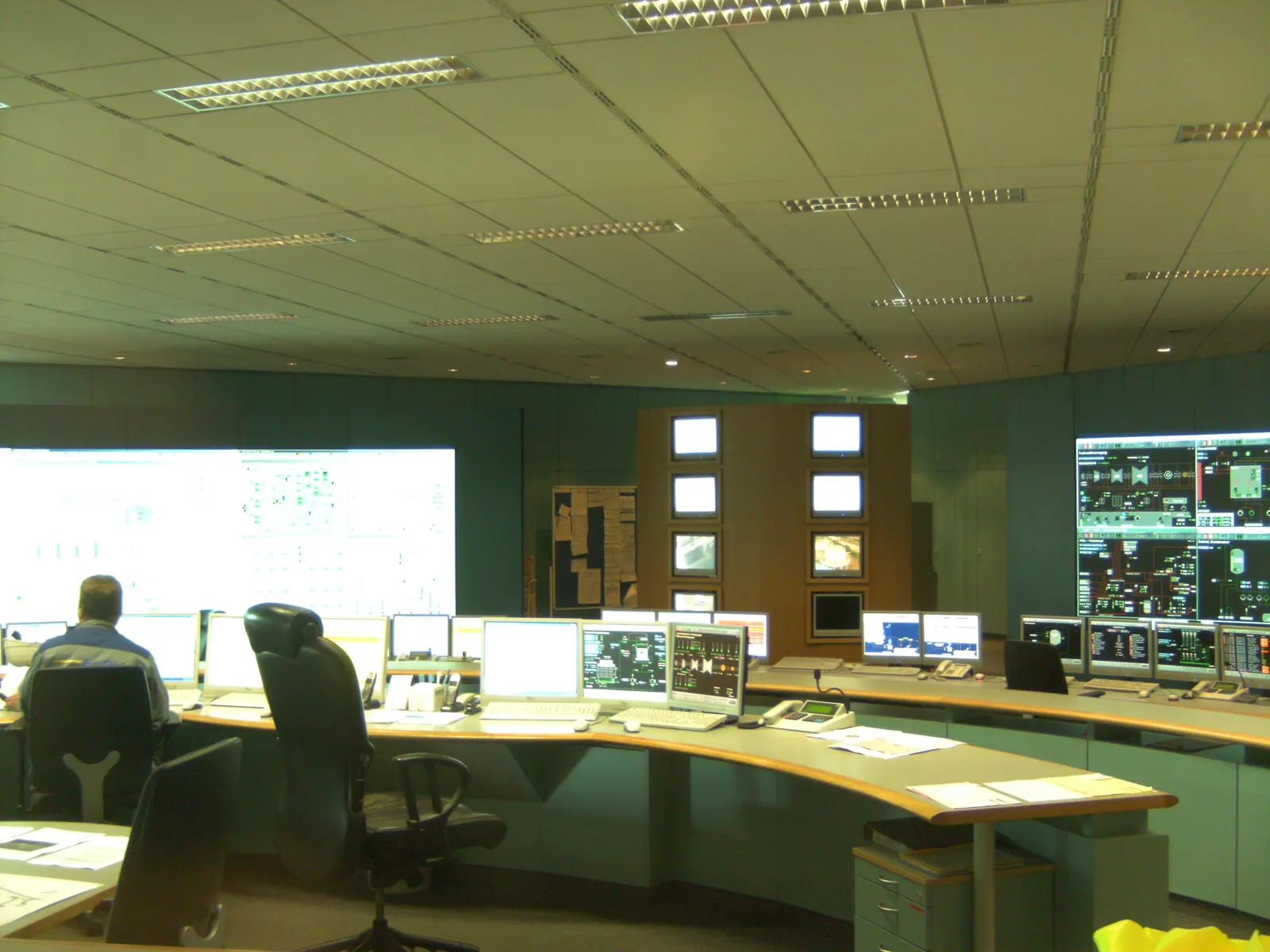
The controls decide whether a cold store saves money. A good controller knows the tariff, the weather forecast and the building's load pattern, charges the store just enough, and discharges it so it is empty exactly when the peak ends.
Electrically, cold storage needs no inverters or batteries. It changes when the chiller motors run, so the main electrical work is the chiller and pump feeders, VFDs, power-quality checks and metering for demand charges.
10.1Control layers
Field
4- Tank temperature string
- Ice inventory sensor
- Flow and BTU meters
- Valve and pump status
Plant controller / BMS
4- Mode selection (charge, discharge, chiller only, both)
- Chiller sequencing and set-points
- Discharge-rate limits
- Alarms and interlocks
Supervisory / EMS
4- Tariff calendar (ToD, solar hours)
- Weather-forecast load prediction
- Demand-limit targets
- Demand-response signals from the DISCOM
10.2Digital and AI tools
01
Load forecasting
Machine-learning models predict next-day cooling load from weather, occupancy and calendar data.
02
Optimal dispatch
Model-predictive control chooses the cheapest hour-by-hour plan for chillers and store.
03
Digital twin
A plant model checks savings, tests control changes before going live and flags drift.
04
Fault detection
Detects fouled coils, poor stratification, glycol loss or stuck valves from trend data.
05
Measurement and verification
Baseline versus actual demand and energy, following IPMVP-style methods.
06
Remote monitoring
Dashboards for kW/TR, TR·h stored, peak shaved and savings, with mobile alerts.
10.3Electrical scope
- LT panels and feeders for chillers, pumps and cooling towers
- VFDs on pumps and tower fans; harmonic check to IEEE 519
- Maximum-demand monitoring and contract-demand review with the DISCOM
- Power and BTU metering for savings verification
- DG and UPS planning for critical-cooling sites
- Earthing, lightning protection and cable sizing to Indian codes
Section 11
Applications and Site Integration
Any site where cooling is a large share of the power bill, or where cooling must never stop, is a candidate. The store is integrated into the existing chilled-water system with a few valves and pumps, or designed into a new plant from the start.
11.1Where cold storage fits
01
Malls, airports, hospitals, hotels
Shift the afternoon peak, downsize chillers in new buildings, and use cheaper night or solar-hour power.
02
District cooling
One central plant and tank serves a business district, smart city, airport or campus through insulated pipes.
03
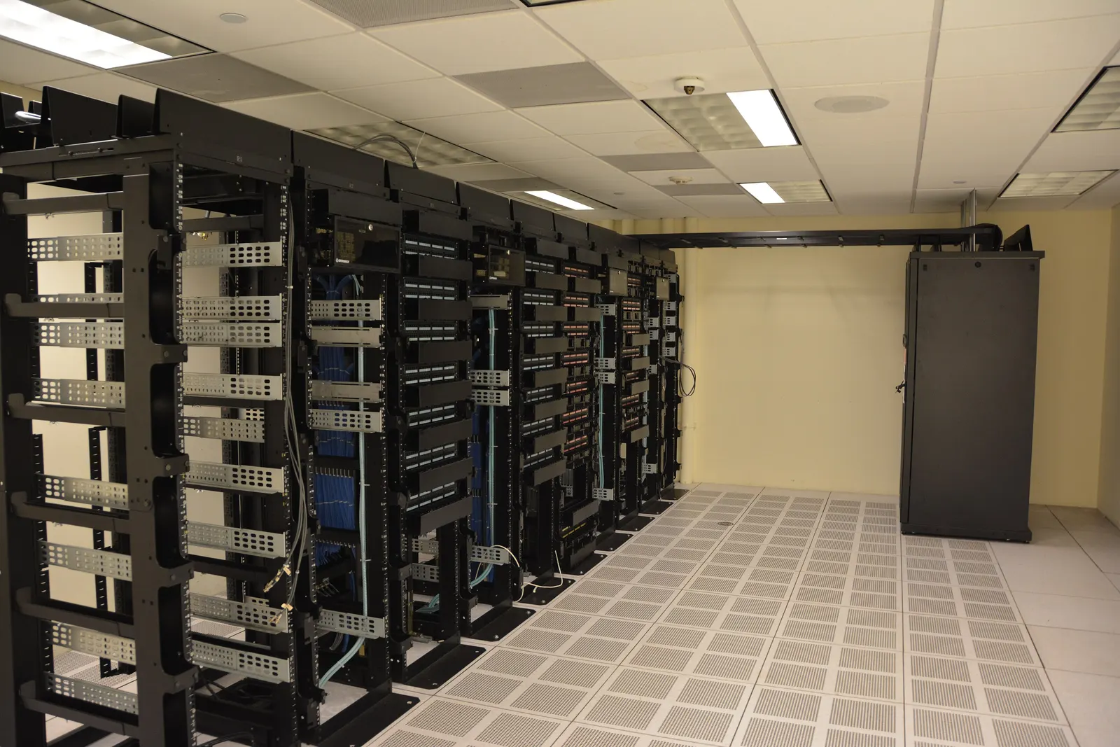
Data centres
Chilled-water tanks give 5–15 minutes (or more) of cooling while chillers restart after a power event.
04
Cold chain
Pack houses, ripening chambers, cold rooms and warehouses for fruit, vegetables, dairy, vaccines and pharma.
05
Process industry
Dairy, beverages, pharma, chemicals, plastics and auto plants with large chilled-water loads.
06
Solar-driven cooling
Store midday solar as ice or chilled water for the evening; cuts export or curtailment.
11.2Data centres and district cooling in more depth
Data centres
5- Cooling is 25–40 % of facility power in older Indian sites
- Tank sized for chiller restart time plus margin
- Pumps on UPS so chilled water keeps flowing
- Works with ASHRAE TC 9.9 allowable inlet ranges
- Also used to shift load in large hyperscale campuses
District cooling
5- Large chilled-water tanks of 10,000–100,000 m³ in the Gulf, Singapore and US campuses
- Tank lets the plant run at steady, efficient load
- Wide ΔT (8–10 K) cuts pipe sizes
- Tariff per TR·h and connection charge to buildings
- India: GIFT City (Gujarat) runs India's first large district cooling network
11.3Integrating with an existing chiller plant
- 1Log 2–4 weeks of hourly chiller load, kW and temperatures
- 2Check spare space (basement, roof, ground) and structural capacity
- 3Choose tie-in points and confirm existing chiller can make ice or needs a new glycol chiller
- 4Add tank, pumps, heat exchanger and mode valves with minimal shutdown
- 5Upgrade BMS sequences and add tariff logic
- 6Commission in stages and verify the peak cut against the baseline
Data-centre and district-cooling figures are typical published ranges; each site's ride-through time and tank size come from its own risk and load study.
Section 12
Civil and Mechanical Works
The tank is the largest structure in a cold-storage project. A chilled-water tank can weigh tens of thousands of tonnes when full, so foundations, seismic design, insulation and waterproofing need the same care as a water-supply reservoir.
12.1Tank construction options
| Option | Typical size | Advantages | Watch-outs |
|---|---|---|---|
| Welded steel, above ground | 1,000–50,000 m³+ | Fast to build, tall (good stratification) | External insulation and cladding; corrosion protection |
| Prestressed concrete (wire-wound) | 5,000–100,000 m³ | Long life, low maintenance, can be partly buried | Specialist contractor; longer build |
| Reinforced concrete pit / basement | 100–10,000 m³ | Uses space under buildings or car parks | Waterproofing, internal insulation, access |
| Modular factory ice tanks | 50–500 TR·h each | Quick install, roof or basement | Floor loading; many connections |
| Bolted / panel tanks | 50–2,000 m³ | Low cost for small sites | Lower height, weaker stratification |
12.2Civil and mechanical design checks
Structure
4- Soil investigation and foundation design
- Hydrostatic, wind and seismic loads (IS 1893, IS 875)
- Liquid-retaining concrete to IS 3370
- Steel tank design to API 650 / AWWA D100 or IS 803
Thermal
4- Insulation thickness for < 1–2 % daily heat gain
- Closed-cell foam or PIR with vapour barrier
- Bottom insulation against ground heat
- Cladding against Indian sun and monsoon
Mechanical
4- Diffuser fabrication and levelling
- Pipe supports, expansion and anchors
- Nozzle and manway design
- Overflow, vent and drain
12.3Site works
- Crane access and laydown area for tank plates or ice modules
- Hydrotest water source and discharge route
- Drainage and bunding around the tank
- Underground pipe routes with insulation and sleeving
- Lightning protection and earthing of steel tanks
- Architectural treatment where the tank is visible
Tank sizes and heat-gain targets are indicative. Codes listed are the usual references; the structural engineer of record selects and applies them for each project.
Section 13
Sizing and Design Calculations
Sizing starts from the hourly cooling load on the design day and the tariff periods. The formulas below give a first estimate; a full design uses 8,760-hour simulations and the OEM's selection data.
13.1Cooling units
TR·h to thermal kWh
E (kWh(th)) = TR·h × 3.517
10,000 TR·h × 3.517 ≈ 35,170 kWh(th) ≈ 35.2 MWh(th)
Indian HVAC quotes storage in ton-hours; engineers often need it in kWh to compare with tariffs and batteries.
| Symbol | Meaning |
|---|---|
| TR·h | Ton-hours of cooling stored |
| 3.517 | kW of cooling per ton of refrigeration |
13.2Chilled-water volume
Tank water volume
V = E ÷ (1.163 × ΔT × FoM)
35,170 kWh ÷ (1.163 × 8 × 0.9) ≈ 4,200 m³ (≈ 3,780 m³ at FoM 1.0)
Each cubic metre of water gives 1.163 kWh per kelvin of temperature difference. Divide by the figure of merit for real-tank losses.
| Symbol | Meaning |
|---|---|
| V | Water volume (m³) |
| E | Stored cooling (kWh(th)) |
| ΔT | Return minus supply (K) |
| FoM | Figure of merit, 0.85–0.95 |
13.3Ice mass and tank volume
Ice needed
m = E × 3,600 ÷ 334 ; V(ice) = m ÷ 917 ; V(tank) = V(ice) ÷ packing factor
35,170 kWh → 379 t of ice → 413 m³ of ice → ≈ 830 m³ of tank at packing 0.5
Ice holds 334 kJ/kg as latent heat and has a density of about 917 kg/m³. Only part of a tank can be ice — coils, capsules and free water take the rest — so a packing factor of about 0.4–0.6 is used.
| Symbol | Meaning |
|---|---|
| m | Mass of ice (kg) |
| 334 | Latent heat of fusion (kJ/kg) |
| 917 | Density of ice (kg/m³) |
| packing factor | Share of tank volume that becomes ice |
13.4Chiller size
Chiller for full storage and for load levelling
Full storage: TR = stored TR·h ÷ charging hours ; Load levelling: TR ≈ daily TR·h ÷ 24
10,000 TR·h ÷ 10 h = 1,000 TR (before ice-duty derating of ≈ 20–35 %)
In full storage the chiller must refill the whole store in the off-peak window. In load levelling the chiller runs all day at the average load and the store covers the difference. A chiller making ice delivers less than its nameplate, so its nominal rating is larger.
| Symbol | Meaning |
|---|---|
| TR | Chiller capacity (tons of refrigeration) |
| charging hours | Hours available to recharge |
13.5Worked example — load levelling
Store for load levelling
Store = Σ (hourly load − chiller TR) over hours when load > chiller
Office: 1,500 TR for 12 h = 18,000 TR·h/day → chiller 750 TR running 24 h → store (1,500 − 750) × 12 = 9,000 TR·h
The chiller halves from 1,500 TR to 750 TR. At night it fills the store with 9,000 TR·h; by day it runs at 750 TR and the store adds the other 750 TR.
| Symbol | Meaning |
|---|---|
| Σ | Sum over the hours |
13.6Peak demand saving
kW taken off the peak
ΔP = TR shifted × whole-plant kW/TR
1,000 TR shifted × 0.9 kW/TR ≈ 900 kW off the peak
Multiply the cooling moved out of the peak by the electricity the whole plant (chillers, pumps, towers) uses per ton. This is what lowers the maximum-demand charge.
| Symbol | Meaning |
|---|---|
| ΔP | Peak demand saved (kW) |
| kW/TR | Whole-plant specific power, typically 0.8–1.2 |
13.7Live estimator
Enter the cooling you want to store (TR·h), the chilled-water temperature difference (K) and the hours available for charging. The estimator returns the stored cooling in kWh(th) (TR·h × 3.517), the chilled-water volume needed (kWh ÷ 1.163 ÷ ΔT), the ice-tank volume (latent heat 334 kJ/kg, ice density 917 kg/m³, packing factor 0.5) and the chiller size in TR to recharge a full store in the charging hours. It is a first estimate only: it ignores the figure of merit, heat gains and ice-duty chiller derating.
Estimate
- Stored cooling
- 70,340 kWh(th)
- Chilled-water tank volume
- 7,562 m³
- Ice tank volume
- 1,654 m³
- Chiller size for full storage
- 2,000 TR
Water 4,186 kJ/m³·K; ice 334 kJ/kg at 917 kg/m³ with a 0.5 packing factor. Ice-making chillers lose some capacity at −5 °C; add tank margin of 10–15 %. Preliminary screening only; BARREL confirms any figure with a site study.
All worked examples use rounded, indicative values. Real designs add heat gain through the tank (1–3 % a day), pump heat, ice-duty derating and a safety margin of 10–15 %.
Section 14
Engineering Deliverables Register
A cold-storage project produces a predictable set of studies, drawings and documents. This register is what BARREL can prepare or check for an owner, consultant or lender.
14.1Typical deliverables
| Stage | Deliverable | Purpose |
|---|---|---|
| Feasibility | Cooling load and tariff study (hourly, 8,760 h where data allow) | Shows the savings and the right strategy |
| Feasibility | Options report: ice, chilled water, PCM, none | Compares cost, space and savings |
| Basic design | Process flow diagram and P&ID | Fixes modes, valves and tie-ins |
| Basic design | Tank sizing and stratification / ice-build calculation | Confirms storage capacity |
| Basic design | Equipment list and data sheets | Chillers, pumps, HX, tank, coils |
| Detailed design | Hydraulic calculation and pump selection | Flow, head and NPSH |
| Detailed design | Civil and structural drawings for the tank | Foundations, walls, seismic |
| Detailed design | Electrical single-line diagram and load list | Feeders, VFDs, metering |
| Detailed design | Control philosophy and sequence of operations | How every mode switches |
| Detailed design | Insulation and heat-gain calculation | Daily standing loss |
| Procurement | Technical specifications and bid evaluation | Fair, comparable bids |
| Construction | Inspection and test plan (ITP), method statements | Quality during build |
| Commissioning | Test procedures, hydrotest, performance test report | Proof of capacity |
| Handover | As-built drawings, O&M manual, M&V baseline | For the operator and auditor |
- PFD
- P&ID
- SLD
- Sequence of operations
- Tank GA
- Diffuser drawings
- ITP
- FAT / SAT
- M&V plan
- As-builts
Section 15
Site Selection and Feasibility
Cold storage pays when there is a large cooling load, a clear gap between peak and off-peak power prices (or a high demand charge), and room for a tank. A short feasibility study answers whether all three are present.
15.1What the study looks at
Load
4- Peak and daily cooling (TR, TR·h)
- Day-to-night ratio
- Seasonal swing
- Future expansion
Tariff
4- ToD peak, normal and solar-hour rates
- Maximum-demand charge (₹/kVA per month)
- Contract demand and penalties
- Open-access or rooftop solar
Space and site
4- Basement, roof, ground or car-park space
- Floor and soil bearing capacity
- Crane and delivery access
- Visual and planning limits
Existing plant
4- Chiller age and type
- Can chillers make ice?
- Pump and pipe capacity
- BMS capability
Risk
4- Need for cooling ride-through
- Water availability and quality
- Fire-water rules
- Downtime allowed for tie-ins
Finance
4- Capex budget or service model
- Payback target
- Subsidies or green-finance options
- Who owns and operates
15.2Quick screening rules (indicative)
| Signal | Good candidate | Weak candidate |
|---|---|---|
| Peak cooling load | Above about 300–500 TR | Below about 100 TR (PCM may still suit) |
| Peak-to-off-peak price gap | ₹2–4/kWh or more | Little or no ToD difference |
| Demand charge | High, and set by the cooling peak | Low, or set by other loads |
| Load shape | Strong afternoon peak, quiet nights | Flat 24-hour load (except for ride-through) |
| Space | Room for a tank or ice modules | No space and no structural margin |
| New build or chiller replacement | Yes — chiller downsizing adds savings | Recently installed oversized chillers |
15.3Feasibility steps
- 1Collect 12 months of power bills and 2–4 weeks of chiller logs
- 2Build the hourly load profile and match it to tariff periods
- 3Screen ice, chilled water and PCM against space and supply temperature
- 4Size options and estimate capex, opex and savings
- 5Sensitivity on tariff changes and load growth
- 6Recommend a configuration and a delivery model
Screening thresholds are rules of thumb only; the actual result depends on the state tariff order and the site's load profile.
Section 16
Turnkey EPC, Packages and Supply Chain in India
Cold storage is delivered like a chiller-plant project with a large civil element. BARREL can take it from study to handover as one turnkey contract, or deliver selected packages with the owner's consultant.
Most equipment is available in India: chillers, pumps, cooling towers, heat exchangers, valves, insulation, steel and concrete tanks are made locally. Ice coils, ice-ball capsules and some PCMs are made in India or imported through OEM partners.
16.1Project phases
- 1Feasibility and option study
- 2Basic design, budget and permits
- 3Detailed engineering
- 4Procurement and factory tests
- 5Civil works and tank construction
- 6Mechanical, electrical and controls installation
- 7Hydrotest, flushing, glycol fill and commissioning
- 8Performance test, handover and M&V
16.2Work packages
| Package | Scope |
|---|---|
| Civil and structural | Soil tests, foundations, tank or pit, plinths, trenches, plant room |
| Storage | Steel / concrete tank, diffusers, ice coils or capsules, insulation, cladding |
| Mechanical | Chillers, pumps, heat exchangers, cooling towers, piping, valves, water treatment |
| Electrical | LT panels, VFDs, cabling, earthing, lighting, metering |
| Controls | PLC / BMS, sensors, SCADA, tariff logic, remote monitoring |
| Testing and commissioning | Hydrotest, flushing, balancing, performance test |
16.3Delivery models
01
Turnkey EPC
One contract, one price, one point of responsibility to handover.
02
EPCM
BARREL manages design and procurement; the owner places contracts.
03
Design-build packages
Storage package alone, tied into an existing plant.
04
Build-own-operate
BARREL or an investor owns the plant and sells cooling per TR·h.
16.4Supply chain in India (indicative)
| Item | Availability | Lead time (indicative) |
|---|---|---|
| Water-cooled and air-cooled chillers | Made in India by several manufacturers | 12–24 weeks |
| Glycol / ice-duty chillers | India and import | 16–30 weeks |
| Pumps, valves, heat exchangers | Made in India | 6–16 weeks |
| Cooling towers | Made in India | 8–14 weeks |
| Steel tank plates, concrete, insulation | Local | Build period 3–9 months |
| Ice-on-coil modules, ice balls | India and import through OEM partners | 12–24 weeks |
| PCM capsules and panels | Indian start-ups and import | 8–20 weeks |
| BMS and PLC hardware | India and import | 6–12 weeks |
Lead times are typical market ranges and change with demand; firm dates come from the purchase orders.
Section 17
Testing, Commissioning and Operations & Maintenance
Commissioning proves that the store holds its rated TR·h and discharges at its rated rate. After that, savings depend on the plant being run to the tariff every day and on water and glycol being kept in good condition.
17.1Testing and commissioning
- 1Factory tests on chillers, pumps and panels (FAT)
- 2Tank hydrotest and leak check; insulation inspection
- 3Pipe flushing, chemical cleaning and passivation
- 4Glycol fill and concentration check
- 5Instrument calibration (temperature string, flow, BTU, level)
- 6Mode-by-mode functional tests of the controls
- 7Full charge and full discharge test on a design-type day
- 8Capacity and stratification report (FoM) or ice-inventory check
- 9Training, O&M manuals and handover
17.2Routine maintenance (indicative)
| Task | Frequency |
|---|---|
| Check charge / discharge log and peak shaved | Daily (automatic report) |
| Water treatment test and dosing | Weekly to monthly |
| Glycol concentration and inhibitor check | Quarterly to six-monthly |
| Tank temperature-string calibration | Yearly |
| Chiller service, tube cleaning | Yearly or as per OEM |
| Insulation and cladding inspection | Yearly |
| Tank internal inspection | Every 5–10 years |
| Control-strategy review against new tariff orders | Yearly or when tariffs change |
17.3Performance indicators to track
- TR·h charged and discharged per day
- Peak kW avoided and maximum demand per month
- Whole-plant kW/TR in charge and discharge modes
- Tank figure of merit or ice-build completeness
- Daily standing loss (heat gain)
- ₹ saved versus baseline, verified each month
Frequencies are typical; the OEM manuals and the site's water quality set the final maintenance plan.
Section 18
Safety and Risk
Ice and chilled-water storage are among the safest forms of energy storage: the medium is water, the temperatures are mild and nothing can burn or explode. The real risks are structural (a very heavy tank), water leakage, glycol handling, refrigerants in the chiller plant, and — for cryogenic systems — extreme cold and pressure.
18.1Hazards and controls
| Hazard | Where | Control |
|---|---|---|
| Structural failure or leak | Large tanks | Proper foundation and seismic design, hydrotest, bunding, inspection |
| Flooding of basements | Pits and basement tanks | Leak detection, sumps, waterproofing, high-level alarms |
| Glycol exposure | Ice systems | Prefer propylene glycol near food; spill kits; labelled pipes |
| Refrigerant leak | Chiller plant rooms | Leak detectors, ventilation, ASHRAE 15 / ISO 5149 practice; ammonia plants need special care |
| Legionella and bacteria | Cooling towers, open tanks | Water treatment, dosing, regular testing |
| Cold burns and asphyxiation | Cryogenic (LNG, liquid nitrogen) | PPE, oxygen monitors, ventilation, PESO-approved vessels |
| Confined spaces | Tank entry | Permit-to-work, gas testing, rescue plan |
| Working at height | Tank roofs | Guard rails, harness, ladders with cages |
18.2Project and business risks
01
Tariff change
A new tariff order may narrow the peak / off-peak gap. Controls must be reprogrammable and savings reviewed yearly.
02
Load change
Tenancy, occupancy or process changes alter the load profile; design with some flexibility.
03
Poor operation
Stores left full or empty at the wrong time save nothing. Automatic control and monitoring are essential.
Section 19
Standards and Compliance
There is no single cold-storage standard; the project follows HVAC, tank, structural, electrical, refrigerant and building codes. The list below shows the usual references in India and abroad.
19.1International references
| Reference | Covers |
|---|---|
| ASHRAE Handbook — HVAC Applications, Thermal Storage chapter | Design of ice, chilled-water and PCM storage |
| ASHRAE Design Guide for Cool Thermal Storage | Detailed sizing and system design |
| ANSI/ASHRAE Standard 150 | Method of testing the performance of cool storage systems |
| AHRI Standard 900 | Performance rating of thermal storage equipment used for cooling |
| ASHRAE Standards 15 and 34 / ISO 5149 | Refrigeration system safety and refrigerant classification |
| API 650, AWWA D100, AWWA D110 / D115 | Welded steel and prestressed concrete water tanks |
| ASHRAE TC 9.9 thermal guidelines | Data-centre temperature ranges |
| ISO 21009 / EN 13458 | Static cryogenic vessels |
19.2Indian codes and regulators
| Reference | Covers |
|---|---|
| National Building Code of India 2016 (Part 8, Building Services) | HVAC, plumbing, fire and building services |
| ECBC 2017 and ECSBC 2024 (Bureau of Energy Efficiency) | Energy efficiency of commercial buildings, including HVAC |
| IS 456, IS 3370 | Reinforced concrete; concrete structures for retaining liquids |
| IS 800, IS 803 | Structural steel; vertical steel storage tanks |
| IS 1893, IS 875 | Seismic and other design loads |
| IS 659, IS 660 | Safety codes for air-conditioning and mechanical refrigeration |
| BEE star labelling for chillers | Chiller efficiency ratings |
| PESO — SMPV (Unfired) Rules 2016 | Cryogenic and pressure vessels, LNG and liquid nitrogen |
| CEA safety regulations and state electrical inspectorate | Electrical installations |
| State fire services | Fire-water use of tanks and plant-room fire safety |
Code editions change; the project specification fixes the edition to be followed. The list is a guide, not a full compliance register.
Section 20
Environment and Circularity
Cold storage itself is water, steel, concrete and insulation — little to worry about. Its environmental value is in letting chillers run more efficiently, absorbing solar power and avoiding peak-hour fossil generation. The main environmental points are refrigerants, water use and end-of-life materials.
20.1Environmental points
Refrigerants
4- Kigali Amendment (2016) phases down HFCs; India ratified in 2021
- India's HFC freeze is due in 2028
- Prefer low-GWP refrigerants (HFOs, ammonia, CO₂, R-290 for small units)
- Leak monitoring and recovery at service
Emissions
4- Shifting load to solar hours cuts CO₂ per TR·h
- Night charging uses cooler condenser water — better chiller efficiency
- Avoided peak capacity on the grid
- Count savings with grid emission factors from CEA
Water
4- Cooling-tower make-up is the main water use
- Tank water is filled once and treated
- Tank can store harvested rainwater or fire water
- Consider air-cooled or hybrid towers in water-scarce areas
20.2End of life and circularity
- Steel tanks and coils are fully recyclable
- Concrete can be crushed and reused as aggregate
- Polyethylene ice tanks and capsules can be recycled
- Glycol can be reclaimed or disposed of by licensed handlers
- PCMs: supplier take-back where offered; salts and paraffins need proper disposal
- Refrigerants recovered and reclaimed, never vented
Phase-down dates follow the Kigali schedule for India's group of countries; check the latest notifications from the Ministry of Environment, Forest and Climate Change (Ozone Cell).
Section 21
Commercial Models, Cost and Investment
Cold storage earns its money from three sources: lower energy charges (buying cooling power at night or solar-hour rates), lower maximum-demand charges, and — in new buildings — smaller chillers, transformers and DG sets. Payback is often 3–7 years in India where the tariff gap is wide.
21.1Indicative installed cost of the storage element
| Medium | Indicative cost (storage only) | Cost trend with size |
|---|---|---|
| Large chilled-water tank (> 20,000 TR·h) | ₹5,000–15,000 per TR·h | Falls sharply with size |
| Small chilled-water tank (< 5,000 TR·h) | ₹12,000–30,000 per TR·h | High per TR·h at small scale |
| Ice-on-coil / encapsulated ice | ₹8,000–25,000 per TR·h | Moderate fall with size |
| PCM systems | ₹15,000–40,000 per TR·h | Depends on material and packaging |
21.2Annual saving
Simple saving estimate
Saving = (kWh shifted × price gap) + (kVA cut × demand charge × 12) − extra kWh × price
900 kW × 6 h × 300 days × ₹3 ≈ ₹49 lakh + 900 kVA × ₹400 × 12 ≈ ₹43 lakh → about ₹90 lakh a year before losses
Energy moved from peak to off-peak earns the tariff gap; the lower peak cuts the monthly demand charge. Subtract the small extra energy for ice-making or tank losses.
| Symbol | Meaning |
|---|---|
| price gap | Peak minus off-peak tariff (₹/kWh) |
| demand charge | ₹ per kVA per month |
| extra kWh | Additional energy for ice-making and losses |
21.3Commercial models
01
Owner capex
The owner buys the plant; BARREL delivers EPC and optional O&M.
02
Cooling-as-a-service
An investor owns the plant; the site pays per TR·h of cooling delivered, with no upfront cost.
03
Shared savings / ESCO
Savings against a verified baseline are shared for a fixed term.
04
District cooling tariff
Connection charge plus capacity and energy charges per TR and TR·h.
05
Green finance
Energy-efficiency loans and green bonds; cold chain can tap government cold-chain schemes.
06
Bundled with solar
Rooftop or open-access solar plus cold store sold as one package.
21.4Investment risks and mitigation
| Risk | Mitigation |
|---|---|
| Tariff gap narrows | Sensitivity analysis; solar-hour strategy; contract with tariff-change clause |
| Load lower than forecast | Measured baseline; modular ice tanks that can be added later |
| Underperformance | Performance test at handover; liquidated damages; M&V each month |
| Customer credit (service models) | Security deposit, escrow, step-in rights |
| Technology risk | Proven media (water, ice) for most projects; PCM only with cycle-test data |
Costs, tariffs and savings are indicative 2024–26 ranges for illustration; actual numbers depend on site, scale, state tariff order and scope. They are not a quotation.
Section 22
India and Global Markets and Policy
India's cooling demand is expected to grow several-fold over the next two decades as incomes rise and summers get hotter. The India Cooling Action Plan, time-of-day tariffs and the cold-chain push all point towards storing cold.
22.1India policy drivers
| Policy | What it says | Why it matters for cold storage |
|---|---|---|
| India Cooling Action Plan (MoEFCC, 2019) | 20-year plan to 2037–38: cut cooling demand 20–25 %, refrigerant demand 25–30 % and cooling energy 25–40 % | Thermal storage and district cooling are among the efficiency levers |
| Electricity (Rights of Consumers) Amendment Rules 2023 | Time-of-day tariff for C&I consumers (from April 2024) and most others (from April 2025); solar-hour rate at least 20 % below normal, peak rate higher | Creates the price gap that cold storage earns |
| ECBC 2017 / ECSBC 2024 | Energy-efficiency rules for commercial buildings | Rewards efficient chiller plants and load management |
| Cold-chain schemes (MoFPI, MIDH, NCCD) | Support for integrated cold chains, pack houses and cold rooms | PCM and ice-bank cold rooms for farm produce |
| Smart Cities and new townships | Planned districts with central utilities | District cooling with large tanks |
| Demand response and DISCOM programmes | Peak-load management pilots | Cold stores are natural, flexible loads |
22.2Global picture
United States
3- Ice storage common in offices since the 1980s
- Many universities run large chilled-water tanks
- Utility demand-charge and rebate programmes
Gulf and Asia
3- Gulf states: large district cooling with chilled-water storage
- Singapore and Malaysia: district cooling in business districts
- China and Korea: policy support for ice storage in buildings
Trends
4- Coupling with solar and heat pumps
- Larger tanks for data-centre campuses
- LNG cold recovery at new terminals
- PCM cold chain for emerging markets
22.3Indian market segments to watch
- Data-centre campuses in Mumbai, Chennai, Hyderabad, Noida and Pune
- Airports, metro depots and large hospitals
- Malls and commercial office parks
- Pharma and vaccine cold chain
- Dairy and farm-produce cold rooms in rural areas
- District cooling in new business districts and GIFT City-style developments
Policy summaries are simplified; read the notified rules and the state tariff order before relying on any figure.
Section 23
Frequently Asked Questions and References
Plain answers to the questions owners and facility managers ask most, and where to read more.
23.1Questions and answers
Is cold storage the same as a battery?
No. It stores cooling, not electricity. But because chillers are a large electric load, shifting cooling to off-peak hours has a similar effect on the bill and the grid, usually at lower cost per kWh shifted.
Does cold storage save energy or only money?
Mostly money — it moves energy to cheaper hours. Ice-making uses a little more energy; chilled-water storage is close to neutral. Night charging with cooler condenser water and steady chiller loading can partly or fully offset the losses.
Ice or chilled water — which is better?
Chilled water is cheaper per TR·h at large scale and uses normal chillers, but needs 3–5 times the space. Ice suits buildings with limited space or a need for very cold supply water.
How big a tank do I need?
Divide the cooling you want to store (TR·h × 3.517 = kWh) by about 9 kWh per m³ for chilled water at 8 K, or about 40–50 kWh per m³ of tank for ice. The live estimator on the Sizing tab does this for you.
What is a TR·h?
One ton of refrigeration for one hour — 3.517 kWh of cooling. A 1,000 TR plant running for 8 hours delivers 8,000 TR·h.
Can my existing chillers make ice?
Some can, with glycol and new set-points, but many standard chillers cannot run below about 4 °C leaving water. A study of the existing plant answers this; often a dedicated ice-duty chiller is added.
How long does the cold last?
A well-insulated tank loses only 1–3 % of its stored cooling a day, so a daily cycle loses very little. Stores are normally cycled every day.
What is the payback?
Typically 3–7 years in India where the peak / off-peak gap and demand charges are significant, and shorter in new buildings where chillers can be downsized. It must be checked against your own tariff.
Does the new time-of-day tariff help?
Yes. The 2023 consumer rules require time-of-day tariffs for commercial and industrial consumers, with cheaper solar hours and dearer peak hours. That gap is what cold storage earns.
Can I charge the store with solar power?
Yes. A store charged during the day from rooftop or open-access solar can cover the evening peak, increasing solar self-use and cutting export or curtailment.
Is it safe?
Ice and chilled water are among the safest storage forms — no fire or explosion risk. The engineering risks are structural loads, leaks, glycol handling and refrigerants, all managed by normal codes.
Can the tank be used for fire water?
Often yes, with the approval of the fire authority and suitable connections, which can save the cost of a separate fire tank.
Why do data centres use chilled-water tanks?
When the power fails, chillers take several minutes to restart even after generators start. A tank, with pumps on UPS, keeps the servers cool during that gap.
What is district cooling?
One central chiller plant makes chilled water and pipes it to many buildings. Large storage tanks let the plant run steadily and cut its peak demand.
What is LNG cold recovery?
LNG at about −162 °C must be warmed to gas at import terminals. Using that cold for air separation, freezing or cooling instead of wasting it to sea water saves energy.
Where do PCMs make sense?
Where a specific temperature must be held without power — vaccine and pharma storage, cold rooms with power cuts, reefer trucks — or where space is too tight for water.
Can I pay per unit of cooling instead of buying the plant?
Yes. In a cooling-as-a-service model an investor owns and runs the plant, and the site pays per TR·h delivered.
How long does a project take?
Modular ice tanks can be installed in 3–6 months; a large chilled-water tank with a new plant typically takes 9–18 months from design to handover.
23.2References and further reading
- International Energy Agency — Space coolingGlobal cooling demand and efficiency
- IRENA — Innovation outlook: thermal energy storageIRENA publications library
- US DOE — Office of Energy Efficiency and Renewable EnergyBuilding technologies and thermal storage
- NREL — National Renewable Energy LaboratoryThermal storage and building research
- ASHRAEHandbook, Design Guide for Cool Thermal Storage, Standard 150
- Bureau of Energy Efficiency (India)ECBC / ECSBC and chiller star labelling
- Ministry of Environment, Forest and Climate Change — Ozone CellIndia Cooling Action Plan and Kigali Amendment
- Central Electricity Authority (India)Regulations and grid emission factors
- Bureau of Indian StandardsIS codes for tanks, concrete and refrigeration safety
- Petroleum and Explosives Safety Organisation (PESO)Pressure and cryogenic vessel rules
Section 24
BARREL Services for Cold Storage
From a load study to a running, monitored cold store. BARREL can work for building owners, developers, data-centre operators, industry, cold-chain businesses and district-cooling promoters, with equipment through OEM partners.
24.1What BARREL can do
01
Energy audit and feasibility
Cooling load profile, tariff analysis, options and savings study.
02
Design
Ice, chilled-water, PCM or cryogenic-cold system sized to your site, with full deliverables.
03
Equipment supply
Tanks, coils, capsules, chillers, pumps and controls through OEM partners.
04
Turnkey EPC
Civil, mechanical, electrical and controls works, testing and handover.
05
Controls and digital
BMS upgrades, tariff-aware control, remote monitoring and M&V.
06
O&M
Daily operation, water and glycol treatment, controls tuning and monthly savings reports.
07
Cooling-as-a-service
Cooling supplied per TR·h with the plant owned and run by BARREL or an investor partner.
08
Owner's engineer
Independent review of designs, bids and performance tests for owners and lenders.
09
Solar plus cold
Rooftop or open-access solar matched with cold storage as one package.
24.2How to start
- 1Share 12 months of power bills and the chiller plant details
- 2BARREL reviews the load and tariff and gives a first view
- 3Agree a feasibility study scope
- 4Receive options, costs and savings
- 5Choose a delivery and commercial model
Project desk
Plan your cold storage project with BARREL
Shift your cooling, cut your peak.
A building, campus, data centre, district cooling scheme, cold chain or LNG cold project — tell us the cooling load and the site, and we will respond with the options and next steps.
Project categories
- Ice storage
- Chilled-water tank
- District cooling
- Data centre cooling reserve
- Cold chain / PCM
- Cryogenic / LNG cold recovery